
You have no items in your shopping cart
Inlet Filters for Mechanical Vacuum Pumps
- Posted on
- Posted in Vacuum Pump
- 2
This article discusses inlet filters that are used on oil sealed mechanical medium vacuum pumps such as rotary vane and rotary piston pumps typically used on vacuum furnaces and, for smaller pumps used for many laboratory and light industrial applications. One of the downsides of any trap is that it will eventually require servicing. Many vacuum system operators prefer not to use traps for that reason. If the correct traps are used and maintenance is planned, the downtime and service costs can be kept in line.
Inlet filters for small mechanical vacuum pumps
There are four types of inlet filters used on vacuum pumps used in laboratories and in light industrial applications:
- Foreline traps
- Catchpots
- Dust traps
- Vapor traps
The first, foreline traps, are used to prevent contamination coming out of the vacuum pump; and the other three are used to prevent contaminants from entering the vacuum pump.
Foreline traps
This type of trap is to prevent oil vapor that moves out of the pump inlet under low pressure conditions when the gas is in molecular flow. That would be at a pressure lower than about 0.1 Torr or 100 microns. The ultimate vacuum of an oil sealed vacuum pump is reached when the hot oil in the pump starts to evaporate. Under these conditions some molecules of oil vapor will backstream from the pump inlet toward the vacuum system. Although back streaming of oil vapor occurs in larger pumps as well, it can be more critical in smaller vacuum systems where the piping is shorter. Instruments such as mass spectrometers, electron microscopes and ultra-high vacuum systems can be contaminated if oil vapor reaches them so most of these instruments use foreline traps. If these instruments become contaminated it can take several days to clean them out and return them to operation.
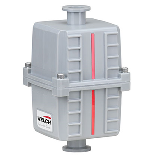
 |
| Fig. 2. Foreline trap, heated |
If the application is cyclic, i.e. it has a short process time, and a number of cycles are run each day backstreaming of oil vapor is less of a problem. It is mostly a problem for processes that are under vacuum for hours on end at low pressure. This situation allows enough backstreaming to take place that contamination may eventually reach the vacuum chamber.
In molecular flow conditions, where back streaming occurs, gas and vapor molecules move in straight lines. A dry gas molecule moving in a vacuum system may collide with other gas molecules depending on the pressure and will also collide with the inner surfaces of the chamber and piping. When a dry gas molecule collides with a surface it resides on that surface for a short time and then releases in a random direction. When an oil vapor molecule leaves the vacuum pump inlet it will move in a straight line until it collides with a surface. Generally it will then stick to that surface and over time be joined by other oil molecules. As the surface becomes “wetter” the oil film will slowly creep along the surface. It is a very slow process but will gradually contaminate the piping and can reach the work chamber.
There is a lot of technical information available that talks about the strengths of atomic bonds between gas and vapor molecules and surfaces and how they vary with temperature. I am not qualified to discuss this physics and will attempt to keep the discussion as simple as possible.
A foreline trap is a device designed to trap or absorb molecules of oil vapor, coming from the pump inlet, and hold them in the filter media and thus preventing them from contaminating the vacuum chamber.
There are two types of material that are used in these traps, molecular sieve and activated alumina. Molecular sieve material is available in spherical and pellet shapes depending on the specification. Activated alumina is generally in spherical form, about 0.250” (.635 cm) diameter. In the vacuum pump industry this material is used to trap oil vapor molecules. However it will also trap water vapor. This is another reason that it is used on very few applications, ones that have little or no water vapor coming from the process. If the trap material becomes loaded with water vapor, less oil vapor can be trapped. These materials are extremely porous and have large internal surface areas that allow oil and water molecules to sorb to the surface. Once sorbed onto the internal surface water vapor is very slow to desorb.
 |
| Fig. 3. Catchpot and/or dust trap |
When the material becomes contaminated with oil vapor it will generally show some light yellow or brown staining. This will tend to be on the pump side of the trap. It is recommended that the stained material be disposed of safely and the trap topped up with new material. The standard trap (Fig. 1) usually has a basket that holds the material, so it can be removed from the trap body for servicing. Old trap material should be heated to above 250°F (121°C) for several hours to drive off any trapped water vapor, before being re-installed in the trap. Other traps available have a built in heater (Fig. 2) so that the trap material can be regenerated “in situ”. When carrying out this operation, ensure
that the trap is isolated from the chamber so that the vapors regenerated go to the vacuum pump. The heated trap that I looked at only heated to 150°F (65.5°C), and may take longer to regenerate.
A suggestion that increases the life of the foreline trap material is to mount the foreline trap nearer the chamber than the pump inlet. Oil vapor coming from the vacuum pump will then condense on the surface of the piping and less will actually reach the trap. This piping should be checked when the trap is serviced and cleaned (degreased) if necessary. Using one or two NW elbows will encourage the oil vapor to collide with a surface before reaching the trap.
Lastly, all molecular sieve and activated alumina products must be kept dry in storage. Placing water loaded material in your vacuum trap will not help your process and will extend the pumpdown time until the contamination is pumped away.
Catchpots
A catchpot is an empty container meant to trap solids such as dust that may come from the system. This will usually occur during the initial pumpdown, when the gas flow has its highest throughput. The initial movement of gas molecules in a large vacuum chamber can be very turbulent and this may cause dust to be transported towards the vacuum pump. The trap is designed to change the direction of the gas flow so that the entrained solids can drop out and stay in the trap. The gas may be directed downwards into the trap or in a circular motion around the inside using an offset inlet (Fig. 3). The opening to the outlet from the trap is placed near the top center of the trap. As the gas flows into the larger volume of the trap its velocity drops allowing any heavier particles to drop out and stay in the trap. The gas will then enter the trap outlet pipe at the top of the trap and flow down and out to the vacuum pump.
Dust traps
 |
| Fig. 4. Dry ice cold trap |
Dust traps have an element inside them to trap solid contaminants. They are available with two different types of element, one for low levels of contaminants and the other for high levels of contaminants. This filter can consist of the catchpot with an added element. This makes good use of the catchpot body, using it for several options.
For low levels of contaminants a pleated paper (Figs. 3 and 6) or polyester element is used. These will eventually become loaded with dirt and reduce the flow of gas through the filter. Each process is different and you will learn from experience how often the element needs to be changed.
When the contaminant level is higher a metal mesh (Fig. 6) or wool element is used which is wetted with oil. This element causes the contaminant to stick to the wetted material but allows the gas to flow through. The mesh will also become loaded, but can be washed and reused. Having a spare clean element ready to go will reduce the service downtime. Typical materials for the wire mesh are stainless steel and brass.
Vapor traps
 |
| Fig. 5. Liquid nitrogen cold trap |
In small vacuum systems vapor traps are seldom used, but may be necessary if the vapor will harm the vacuum pump by contaminating the pump oil. For many applications, where a small amount of water vapor is present we can use the gas ballast valve on the vacuum pump to keep the pump oil clean.
Degassing is an industrial process where heavy vapors should be trapped before they enter the vacuum pump. Urethanes, varnishes and resins will evaporate when being degassed and these vapors can affect the pump oil and clog the small oil ways in the pump mechanism. The filter media used for this would generally be activated charcoal granules which absorb the heavy vapor. In my experience few companies who have degassing systems use an inlet trap due, I think, to the cost of the trapping media and the time involved. They tend to rely on frequent oil changes and hope that the pump doesn’t fail.
Freeze drying is one process where a water vapor trap is always used, but other laboratory processes where liquids are involved may or may not use a vapor trap to protect the vacuum pump.
In a freeze dryer the “vapor trap” is a built in refrigerated condenser between the drying chamber and the vacuum pumps. As the water vapor sublimes from the frozen product it moves towards the vacuum pumps buts freezes on the condenser to prevent contamination of the pump. Sublimation is the process where, under vacuum, the water in the frozen state will change directly to vapor (sublime) without going to liquid first.
In laboratories vapor traps are often used for short periods of time. If the process is longer than a few hours there may be a need to refill the vapor trap or cold trap as it is often called. If a cold trap is left to warm up the frozen contaminants will thaw, evaporate and enter the pump.
One style uses a slurry of dry ice and isopropyl alcohol or acetone a short term cold trap. It cools to about -109°F (-75°C). This type of trap (Fig. 4) has a top loaded container for the dry ice slurry with a loose lid covering the top of the container. The lid reduces the boil off of the coolant and allows for easy filling and topping up. The slurry container is positioned in the center of a larger circular container that produces an interspace around the cold trap where the gas can flow. Usually standard NW type vacuum connections are used to connect the trap to the vacuum pump.
Liquid nitrogen traps (Fig. 5) can also be used which have a slightly different design. The LN2 container is positioned in the center of the trap as before, but the fill connection is a smaller spout, rather than a lid.
Some traps have two spouts allowing boil off to exhaust through one spout during refill through the other spout. This is a safer design as it eliminates splashing than can occur when using just one spout.
Liquid nitrogen boils off at -321°F (-196°C).
Remember to follow all safety rules when using these very cold liquids. Gloves and facemasks are recommended when filling or topping up.
Inlet filters for large industrial applications
 |
| Fig. 6. Pleated and Mesh elements |
In these applications that are mostly cyclic, the main problem is “dust” or fine particulate matter entering the vacuum pump. Systems that are processing metal parts and have heating zones in the main chamber tend to be dusty. The standard rotary piston design can experience severe wear on the lower hinge bar (Stokes) or slide pin (Kinney). The inlet area of the pump is very wet with oil and any particulate will tend to accumulate in this area and cause damage to the sliding surfaces.
Both manufacturers caution pump users to be particularly cautious when a system is started for the first time. Inlet piping and even the main chamber can be contaminated by all sorts of debris if not cleaned carefully prior to the start of a vacuum pumpdown. They suggest a fine mesh filter plate be installed near the pump inlet to catch this debris on the first startup and until no more is apparent.
For processes that are dusty a permanent inline dust filter should be used. The smaller sizes can possibly be supported by the vacuum inlet line, but larger sizes (Fig. 7) will have legs or a base to support them. Inlet filters always have the gas stream enter the outer body of the trap, pass through the filter element from outside to inside, and then exit the trap towards the vacuum pump. The manufacturers of these traps may offer several types of element for different applications, but a pleated paper or polyester element appears to be the element of choice for dusty applications. The pleating of the element makes a large surface area available for the gas to pass through. You will have to determine by experience how long an element will last on your particular application.
 |
| Fig. 7. Large inlet dust trap |
Strangely, when researching for this article, the main rotary piston pump manufacturers don’t appear to offer inlet filters. It was difficult to find details on sizes offered from anyone and although I did find a couple of possible suppliers their websites offered little information. If anyone has information on large inlet dust filters in the 200 cfm to 1000 cfm size, I would be happy to hear from you.
Some large vacuum pump applications do use vapor traps or condensers on the inlet side of the vacuum pump. These applications are more suited to “rough vacuum” applications such as the chemical process industry where different types of vacuum pumps are used. They are seldom used on the oil sealed rotary piston type vacuum pump.
As with previous Vacuum Pump Practice articles the author welcomes your comments and also suggestions for future articles. Thanks also to those that have contacted me with requests and questions.
Acknowledgements:
Pictures of products described in this article were copied from the internet or from manufacturer websites. Thanks to MDC, Nor-cal Products, Edwards Vacuum and Laco Technologies for products that I was able to identify. Technical training material developed by the author.
Copyright Howard Tring, Tring Enterprises LLC Vacuum & Low-Pressure Consulting.
Comments
Be the first to comment...