
You have no items in your shopping cart
Oil Diffusion Pump Controls
- Posted on
- Posted in Vacuum Pump
- 0
Introduction
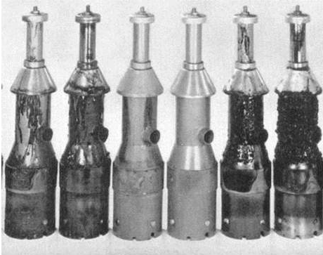
 |
| Fig. 1 Large Oil Diffusion Pumps. |
Oil diffusion pumps are an old technology that remain popular in certain industries. The main reasons for their continued use are their simplicity, cost, and durability.
When your process requires a pressure below that of a mechanical pump or mechanical pump and Roots pump combination a secondary vacuum pump has to be used. These are oil diffusion pumps, turbomolecular pumps and possibly cryogenic pumps.
Turbomolecular pumps are limited in physical size due to the high rotor speeds needed to create molecular flow into the pump mechanism; and both “turbos” and “cryos” are very susceptible to process contamination. Large cryos are often used in vacuum coating applications.
I think that many oil diffusion pumps are still used for industrial and some scientific applications in the eastern parts of the world where the cost of a turbomolecular pump is still very high based on the local costs of doing business.
In this discussion I am not going to explain how an oil diffusion pump works, as there are several articles explaining these basics. For example, the textbook “High-Vacuum Technology” by Mars Hablanian (retired from Varian Vacuum Products, now part of Agilent) contains a 70 page chapter on diffusion pumps that is very comprehensive. See Fig. 1 for different designs of large oil diffusion pumps.
What I will talk about this time are some facts about diffusion pump operation and the accessories and instruments that are used to ensure that the diffusion pump works as it should without causing too much contamination of the system.
Diffusion Pump fluids
Early diffusion pumps used mercury as the operating fluid but mercury is a toxic material and causes many problems. When I started selling vacuum equipment in Canada in the early 80s, we were replacing mercury diffusion pumps on mass spectrometers with pumps designed for mainly Santovac 5 (polyphenylether) fluid. Santovac 5 is the preferred fluid in these applications because it produces a lower pressure and does not polymerize to an insulating layer as silicone fluids can in some processes.
 |
| Fig. 2. Oxidation of Jet Assemblies. |
For larger diffusion pumps, those used in the vacuum heat treating and vacuum deposition industries, the original replacement fluids for mercury were hydrocarbon oils. Although less hazardous than mercury, hydrocarbon oils are very susceptible to oxidation if they see any oxygen molecules i.e. at higher pressures. When hydrocarbon oils oxidize they create a thick black tarry contaminant. In a diffusion pump this tends to accumulate around the jet areas of the jet assembly, Fig.2. This is where the hot oil vapor from the pump boiler first meets molecules of oxygen entering from the vacuum chamber. It is quite easy to understand that this buildup of contamination will cause the jets of the vacuum pump to lose efficiency. The vapor stream from the jets will not form properly and this will make any backstreaming of oil vapor worse.
Fig. 2 is thought to be from a Dow Corning advertisement for their new (at the time) silicone fluids. The jets assemblies in the center were used with silicone fluid and remained quite clean and the others had been used with hydrocarbon oils and were more contaminated by oxidation of the fluid.
It appears that hydrocarbon oils may still be in use in Europe as a recent paper by Oerlikon Leybold says that there may be power saving options when using these fluids. They suggest that in a cyclic application, such as most single chamber vacuum heat treating systems, power can be saved between cycles by reducing the fluid temperature when unloading and reloading the chamber and the diffusion pump is isolated from the chamber but still hot and under vacuum.
I believe that most oil diffusion pumps in the USA use silicone fluids as the preferred fluid. They are safer and are less prone to oxidation. Typical grades are 702, 704 and 705 depending on the ultimate vacuum required.
Diffusion pump controls.
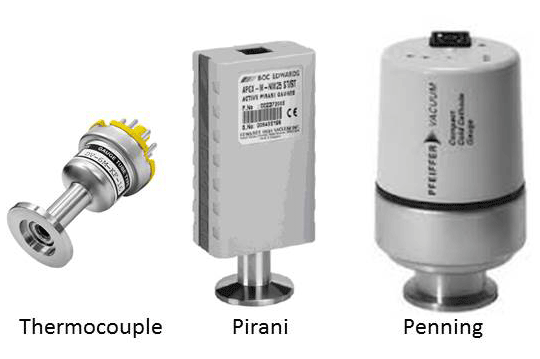 |
| Fig. 3. Traditional Vacuum Gauge Heads. |
There are several parameters to control and monitor on an oil diffusion pump system.
- Electricity is used for the heaters under or in the boiler
- Cooling water is used to cool the outer body of the diffusion pump and also the cold cap mounted over the top jet inside the pump
- The fluid vapor temperature can be monitored to indicate that the pump is pumping
- Pressure also has to be monitored and pressure changes can be used to control both the process and the pump system. Vacuum gauges are mounted in at least three positions
- On the chamber to monitor roughing pressure
- On the chamber to monitor high vacuum pressure
- On the backing line to monitor the pressure at the exhaust of the diffusion pump
- (Possibly a gauge head or a valved off connection near the inlets of the roughing pump and the holding pump)
Electricity
The amount of power needed is determined by the size of the diffusion pumps and its rated heater watts. Large diffusion pumps may have from three to eight heaters fitted close to the boiler plate. Both the boiler plate and the heaters should have flat and smooth surfaces for good contact and to eliminate hot spots. One manufacturer mounts heaters inside the boiler as they see this as more efficient. There is generally no variable control of this power.
Cooling Water
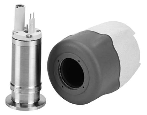 |
| Fig. 4. Pirani/Penning wide range gauge head. |
Cooling water is supplied to the cooling coils on the outside of the diffusion pump body.
It is also used to indirectly cool the cold cap accessory mounted over the top jet of the pump interior. These circuits can be in series, or parallel. The colder the cold cap the more efficient it is so parallel circuits may be best. The cooling water flow is set using the manufacturer’s suggested pressure and flow and then adjusting the flow to give the specified temperature rise between inlet and drain.
One sensor supplied as an accessory is a cooling fail thermal switch, mounted on the lower coils of the pump body. This switch is to cut power to the heaters if there is a water failure and the pump becomes overheated.
Diffusion pumps can also have a “pump ready” sensor to indicate that the fluid has boiled and the vapor jets are working. This switch is mounted on the exhaust line of the diffusion directly opposite the ejector jet in the interior assembly. When the hot fluid is exhausted from the pump body towards the exhaust flange it heats up this area until the switch is activated to indicate “pump ready. Usually the manufacturer will also state how many minutes it takes for the pump fluid to boil.
Pressure (vacuum) Gauge Heads
The vacuum gauge heads or sensors (Fig. 3) allow the main controller to automatically run the system through its process steps. If any pressure reading is not within its control parameters, the process will not continue.
The roughing vacuum gauge head can be a Thermocouple/Thermistor, a Pirani or a capacitance manometer depending on the process and the system specification. It monitors the chamber roughing pressure and once the chamber pressure is below the diffusion pump crossover pressure it will allow the roughing valve to close. It can be mounted in the roughing line close to the chamber, but is best mounted right on the chamber, close to the high vacuum gauge head.
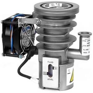
 |
| Fig. 5. Diffusion pump high vacuum valve. |
If the backing line vacuum gauge reading is correct the backing line valve will then open and the diffusion pump will be pumped by both the large roughing pump and the small holding pump (assuming that a holding pump is installed on the system). In most case the holding pump is left running. There would be a small power saving if it was shut off.
The backing pressure gauge head can be the same types as the roughing line gauge head, as it is reading mechanical pump pressures. It can be an advantage if this gauge head has a set point. Read below about critical backing pressure and controlling the opening of the high vacuum valve.
The chamber high vacuum gauge head must be selected to suit the base pressure, the process pressure and to withstand any process contamination. The inlet to the gauge head should be shielded from any direct line of sight to the process. Penning gauges are rugged mechanical gauge heads that can be mechanically cleaned if they become contaminated. It is important the Penning gauge head is not on above about 10-2 Torr as the interior can become oxidized. The gauge controller usually switches it on as the pressure drops and off as the pressure rises to prevent this problem. New designs of ion gauge heads have made them more suitable for rugged processes, and they read lower pressures than the Penning gauge. Depending on the system pressure a capacitance manometer may also be selected. Capacitance manometer gauges are the most accurate of all vacuum gauges and corrosion resistant. Some gauge suppliers also offer combination gauges where there are two methods of reading the pressure in one gauge head envelope; for example a Pirani/Penning or Thermocouple/Penning combination (Fig. 4). These newer gauges have also been made smaller and the electronic readouts have been linearized to make automation of the process a bit easier.
High Vacuum Valve pneumatic cylinder control
This step of the process is very important to keep the diffusion pump working correctly. It is the opening of the high vacuum valve to start pumping the main chamber through the diffusion pump.
I think that this step may be one of the least understood parts of the process and is the main point of this article.
The high vacuum valve is generally a large right angled elbow with a poppet valve mounted near the lower flange close to the diffusion pump. The valve is opened and closed using a vertically mounted pneumatic cylinder on the top of the elbow (Fig. 5).
In many systems there may be a baffle valve and/or cold trap installed between the diffusion pump and the high vacuum valve. They are installed to reduce backstreaming of hot oil vapor from the diffusion pump. They may be cooled by city water, refrigeration or LN2. The pump manufacturers offer suitable baffles and traps for their pumps and there are also other suppliers that offer similar accessories.
 |
| Fig. 6. Critical backing pressures. |
In the early days of high vacuum systems the vacuum pump manufacturers made the high vacuum valves to suit their own diffusion pump. The design used by Edwards had a horizontal shaft across the vertical cylinder section of high vacuum valve, directly above the diffusion pump, that was turned using a lever by a pneumatic cylinder. There was a linkage connecting the inner part of the shaft to the valve plate. As the pneumatic cylinder moved the lever to turn the shaft the inner linkage lifted or lowered the valve plate. Modern designs generally use the vertically moving poppet valve as a simpler mechanism and the system manufacturers now usually fabricate their own high vacuum valves.
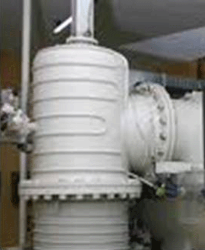
When the valve plate opens it is very important that it opens slowly. The oil diffusion pump is pumping low pressure gas at a speed measured in thousands of liters per second. To prevent the critical backing pressure of the diffusion pump from being exceeded the high vacuum valve must throttle the flow of gas into the diffusion pump for the first few seconds.
At the point when the high vacuum valve opens the mass of gas that can enter the pump is at its highest. The chamber pressure is around the crossover pressure specified and the gas is at its highest density and pressure that the diffusion pump should see. In fact the maximum throughput at this time is higher than the pump rating. The only way to prevent the vapor jets from stalling is to throttle the gas flow into the pump until the pressure has dropped enough that the throughput can be pumped away by correct operation of the pump set. Then the valve can be fully open for maxium pumping speed.
If the high vacuum valve opens too quickly the inrush of gas cannot be pumped away by the backing pumps quickly enough. That causes the backing pressure to rise above the critical backing pressure of the diffusion pump, and this will cause the vapor jets inside the diffusion pump to stall. The jets are just vapor and cannot push into a pressure higher than the critical backing pressure (Fig. 6).
In the short time that this may occur, the jets continue to stream hot vapor into the outer diffusion pump volume. This vapor has nowhere to go but up towards the vacuum chamber. It will contaminate the baffle, the high vacuum valve and possibly reach the vacuum chamber.
 |
| Fig. 7 Adjustable air flow muffler. |
So the problem, as I see it, is that the correct operation of the diffusion pump, when the high vacuum valve is opened, is relying on the opening speed of a component (the high vacuum valve) not made by the pump supplier and that may or may not be controlled correctly.
As stated earlier, the high vacuum valve is opened using a vertical pneumatic cylinder, mounted on top of the valve body, which lifts the valve plate off its seat. The flow of compressed air in and out of the pneumatic cylinder is in turn controlled by an electric solenoid valve. This electric solenoid valve is the critical item in this part of the process. The flow of air into the cylinder to lift the valve plate must be limited to ensure that the valve plate lifts slowly enough that the critical backing pressure on the backing line vacuum gauge head is not exceeded. This requires some trial and error setting to ensure that it works correctly, and should be checked frequently.
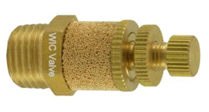
To make this control a bit more difficult the flow of air into the pneumatic cylinder is not controlled, it is the air exhausting from the opposite side of the cylinder piston that is usually controlled. This is carried out by installing an adjustable exhaust muffler (Fig. 7) on the exhaust connection of the electric solenoid to reduce the exhaust flow from the cylinder.
The movement of the cylinder piston upwards, to open the valve, is slowed down by restricting the exhaust flow from the low pressure side of the piston. This small device, with a simple adjusting screw and lock nut, is used to ensure the diffusion pump is not overloaded when opening the high vacuum valve. Lastly, is it probably installed on the top of the high vacuum valve and may not be easy to reach.
At the end of the process, when the high vacuum valve is closed, it does not need any flow control of the compressed air. The valve can be shut using the full flow and no adjustable muffler is used.
It is possible to use a vacuum gauge head with a control set point as the backing line sensor. This set point can be used to stop the opening of the high vacuum valve if the backing line pressure approaches the critical backing pressure. I do not know if any vacuum furnace systems use this feature, but it prevents the possibility of chamber contamination.
Final note and suggestion
High vacuum valves may be set up and controlled so that they open slowly and the diffusion pumps do not stall when the high vacuum valve is opened. It is a part of the control that I do not think is understood very well and I wanted to discuss it with the readers.
However, if you are an operator or a maintenance technician, you should know about all the sensors on your system and how the opening of the high vacuum valve is controlled. If manufacturers use the method described or other methods of ensuring correct operation I would be happy to hear about it from you.
Copyright Howard Tring, Tring Enterprises LLC Vacuum & Low-Pressure Consulting.
Comments
Be the first to comment...