
You have no items in your shopping cart
The Oil Sealed Rotary Vane Vacuum Pump-Background History and Designs
- Posted on
- Posted in Vacuum Pump
- 2
The background and history of the rotary vane pump design
Belt drive design
This article discusses one and two-stage “medium vacuum” oil sealed rotary vane vacuum pumps that can produce a catalog ultimate vacuum of about 1 x 10⁻² Torr (0.01 Torr or 10 microns) for a one stage model and about 1 x 10⁻³ Torr (0.001 Torr or 1 micron) for a two-stage model.
Oil sealed rotary vane vacuum pumps are used in the vacuum heat treating and vacuum furnace industry as holding pumps at the exhaust side of the oil diffusion pump. They keep the exhaust line pressure low enough to prevent stalling of the oil diffusion pump while the larger mechanical pumps are roughing (evacuating from atmospheric pressure) the main vacuum chamber.
In the early days, pre-second world war, there were also oil sealed rotary cam pumps designs, such as the “world famous Cenco ‘Hyvac’ two-stage vacuum pump (Fig. 1) and the Nelson Pump Co. ‘Nevaco’ vacuum pump (a). Although the Hyvac pumps and other Cenco models are still manufactured today by HyVac Products, PA, the Nelson Pump Company was bought by Ace Pump, TN, and their vacuum pumps are no longer made.
 |
| Fig. 1. Cenco “HyVac” vacuum pump. |
There are other oil lubricated rotary vane vacuum pumps made, usually by different manufacturers, that are not sealed (sometimes referred to as “flooded”) with oil. These vacuum pumps allow limited oil into the pump for lubrication and generally produce a best vacuum of around 0.5 Torr. This is not a low enough pressure for many industrial and scientific applications, especially those using an oil diffusion pump, a turbomolecular pump or a cryogenic pump for high vacuum pumping..
Early Rotary Vane Oil Sealed Vacuum Pumps (belt drive)
Rotary vane oil sealed vacuum pumps (RVOSVPs) were originally belt driven. The pump was mounted on a baseplate with an electric motor on a slide base installed next to it. The pump was driven through vee belts on pulleys mounted to the pump and motor. Pulleys of different sizes allowed the rotating speed of the pump to be set, usually around the 500 to 600 rpm area, about a third of the electric motor speed. The slide base allowed the vee belt tension to be adjusted. Later on, as safety standards were introduced, the vee belts and pulleys had to be covered by a metal cover.
Due to the relatively low rotational speed of the pump rotor, the blades or vanes were generally made of steel in the hope that centripetal force would throw them outwards to contact the inside of the stator and make a seal. To make sure this happened, holes were drilled on the inner edge of the blades and springs were inserted. Often steel pins were added inside the spring to reduce the flexing and prevent buckling.
At Edwards, they also used molded asbestos/resin blades and this made the springs and pins more important. The springs because the blades were lighter than the steel ones and require a positive force to ensure contact with the stator; and the pins because a flexing spring could wear through the side of a molded blade creating lots of damage.
There were many manufacturers of RVOSVPs in North America and in Europe and up until the 1950s, most manufacturers sold their products generally in their own local markets. There were few European made vacuum pumps sold in North America and most likely, few North American made vacuum pumps sold in Europe. One of the reasons for this could have been the different electrical power supplies, i.e. 60 Hz 115 V in NA and 50 Hz 230 V in EU. That problem wasn’t too difficult to deal with when most of the vacuum pumps were driven by vee belts as the motor was a separate item. In fact, Edwards in the UK sold larger US made Kinney rotary piston pumps before they designed their own large rotary piston pumps. Another reason, in my opinion, was the time and cost of travel between the two continents and extended shipping times by sea.
 |
| Fig. 2. Welch DuoSeal vacuum pump. |
The most popular design of oil sealed rotary vane pumps became a modified version of the Gaede design from 1907 (Fig. 3). Welch Scientific introduced the Wegner Micro-Deka in 1934 which was an improvement on the Gaede design (b). This improvement was the oil seal between the gas inlet and exhaust openings in the stator. This area of the stator was machined at the same diameter as the rotor, therefore, producing a narrow band between the rotor and stator that would hold oil in it when the clearance was around 0.002 inches. Too little clearance would allow metal to metal contact, and too much clearance would allow the higher pressure gas on the exhaust side of the seal blow the oil out of the sealing area and allow gas leakage across the seal. This seal design is known as an arcuate seal. Welch trademarked the name “DuoSeal” and continues to use that trade name today for its vee belt driven oil sealed rotary vane vacuum pumps. (Fig. 2) Most other manufacturers also used this arcuate seal design as it has proved to be very robust.
With the clearance set at the correct amount the pump blade (or vane), which tends to sweep a small volume of oil in front of it at the tip area, adds this oil to the arcuate seal on the exhaust side and a similar amount of oil would be expelled from the seal area on the inlet side. This means that the oil in this seal area is constantly being changed. The oil being pushed into the arcuate seal causes a distinctive noise on some models of this pump design. Once the pump has run for a minute or so, on a small volume, and the “slap-slap” or “clack-clack” can be heard the pump should be giving a good vacuum (low pressure).
Pros and Cons of Vee Belt Drive vacuum pumps
For some vacuum pump users, especially in quiet laboratory settings, this “slap-slap” or “clack-clack” noise is objectionable and the sound can be reduced by cracking open the gas ballast valve a small amount and letting a small amount of air into the pump. Cracking open the gas ballast valve can cause additional oil mist to be generated from the exhaust of the pump requiring the use of an oil mist filter.
As I mentioned the gas ballast valve a short comment about it is necessary. On early oil sealed rotary vane vacuum pumps there was no gas ballast valve. Not until around 1953 on Edwards UK made vbd pumps (Fig. 4). In those days if the application caused water vapor to be drawn into the vacuum pump and it was enough to condense in the pump oil and to dilute the oil, its lubrication and sealing properties were adversely affected. If a water and oil mixture is left in the pump corrosion will occur and the life of the pump will be compromised.
 |
| Fig. 3. Gaede 1907 design. |
The cure before there was a gas ballast valve was to add a vapor trap on the pump inlet. The trap I am familiar with, supplied by Edwards, was a multi-tray trap containing phosphorous pentoxide (P2O5) that looks like a white powder. When water vapor reacts with the P2O5 it changes the surface powder to a wet material, phosphoric acid. The material in the trays could be stirred once or twice to bring dry powder to the surface before having to replace the material altogether. It was typically rinsed down the closest sink. This would not be allowed these days of course.
Once the gas ballast valve was invented it first became an optional accessory and then a permanent part of any pump of this type. As a refresher for you, allowing a bleed (ballast) of air (or inert gas in some applications) into the exhaust valve area of the pump allows water vapor to be expelled out of the pump as vapor before it is compressed enough to reach its vapor pressure and condense into a water droplet that will mix into the pump oil. Oil that appears to be an emulsion of milky white liquid with green streaks is the obvious sign of major oil contamination by water.
Most early vee belt drive pumps had an oil lubrication circuit that relied on oil from the “filled to the top” oil box draining through a small hole in the top of the pump by gravity through passageways to the bearings, rotor, and stators. These small laboratory sized vacuum pumps do not have ball bearings supporting the rotor. The rotors are relatively light and the vacuum pump only creates very small radial and axial loads so that a simple metal to metal with an oil film bearing will support the rotor. The bearings are straight sections at each end of the rotor that match bored holes in the stator and have close tolerances to hold an oil film between the surfaces. This is the main reason that this design of vacuum pump needs to have clean oil in it at all times. Any contamination can affect the bearing surfaces and lead to pump failure.
A drawback of the simple gravity drain oil circuit is a problem called “suck back” of oil.
If the pump stops either deliberately or due to a power failure it leaves the pump inlet open to the system which is under vacuum. In that event suck back of oil can occur. Atmospheric pressure acting on the oil surface in the oil box slowly pushes oil down the gravity drain opening, into the pump mechanism and towards the inlet side of the pump which is at low pressure. If the amount of oil is large and the system is close to the pump inlet it is possible to have oil “sucked back” into the system causing contamination. Gravity drain lubrication requires lots of oil above the top of the pump oil inlet hole to make it work, hence the problem. An ideal pump set up is one where the vacuum pump is isolated from the vacuum system on shutdown and then the pump interior is allowed to go to atmospheric pressure. This minimizes the chance of oil draining into the pump mechanism.
This “suck back” problem requires vacuum pump users to install an automatic shut off valve on the vacuum pump inlet that to prevent any oil from getting past it. One simple non-return valve, used by Edwards, was a lightweight ball inside a housing with an angled top, inside. If oil was drawn towards the system the ball would float until it sealed against the angled inside face. This was not 100% foolproof but worked quite well. A later option was a magnetic solenoid valve that would close on power failure to give a secure seal. A downside of any of these accessories was the space taken up on top of the pump. In many cases, an equipment designer had limited space inside a framework to fit the vacuum pump. Adding these accessories took up another three or four inches of space.
Another problem caused by oil draining down into the open volume of the stator occurs when restarting the vacuum pump. When the vacuum pump is pumping gas the gas is compressed through the relatively small exhaust valves of the pump. Trying to expel oil through those same small holes is more difficult because the oil is not compressible. On a vee belt drive pump it can cause the vee belts to slip on the pulleys and possibly burn out, or it can cause the electric motor to overload its thermal protection device or fuses and shut off.
 |
| Fig. 4. Edwards vbd pumps. |
The main positive feature of slow running vee belt drive rotary vane vacuum pumps is their ability to dilute contaminants in the large volume of oil and keep running despite the contamination. Their running temperature is generally lower than that of faster running direct drive vacuum pumps and they are a simple rugged machine. They are still popular in applications such as wet chemistry laboratories where the chance of ingesting a variety of chemical contaminants is high.
Vee belt driven vacuum pumps were labor intensive to assemble, with the baseplate, pump, motor, pulleys, vee belts and beltguard making it time-consuming in the final assembly area. In the 50s and 60s, the tremendous growth of industry and scientific research applications caused the vacuum pump manufacturers to rethink their designs. There was a push for compactness and a need to reduce manufacturing costs to stay competitive. The age of direct drive vacuum pumps was near.
US manufacturers of vee belt driven rotary vane oil sealed vacuum pumps.
There were a number of companies making these pumps from the 1920s up into the 1970s and 1980s and most have either been taken over by other companies or are out of business altogether. Here are some names that you may or may not have heard of:
- Arthur F. Smith, sold to All Starr Scientific (out of business)
- Central Scientific Co. (Cenco), sold to Boekel and again in 1990 to HyVac Products (still made)
- Marvac Scientific Mfg Co. (closed vacuum pump division in 2003)
- Precision Scientific, sold to GCA Corp and again in 1966 by Jouan (no longer made)
- Red Point Corp. discontinued vacuum pumps in the mid 1970s
- Robinair, now a division of SPX, now make small direct drive pumps for A/C and refrigeration use
- W M Welch Scientific, merged with EH Sargent, bought by Thomas Industries and then in turn bought by Gardner Denver. Welch DuoSeal seal pumps are still manufactured and have been modernized.
In the following section, I will discuss the move to direct drive oil sealed rotary vane vacuum pumps and the design changes that were part of it.
Direct Drive design
As stated above, this article talks only about one and two-stage “medium vacuum” oil sealed rotary vane vacuum pumps that can produce a catalog ultimate vacuum of about 1 x 10⁻² Torr (0.01 Torr or 10 microns) for a one stage model and about 1 x 10⁻³ Torr (0.001 Torr or 1 micron) for a two-stage model.
Smaller vacuum pumps such as those used in the heating, ventilating and air conditioning industry (HVAC) are not included as they are often only for intermittent use and do not have the design features built into the laboratory sized continuous running vacuum pumps used in industry and science.
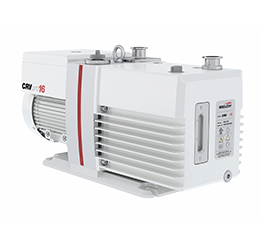
 |
| Fig. 1 Direct Drive vacuum pumps. |
Larger rotary vane vacuum pumps, ones that require ball or roller bearings to support the weight of the rotor are not included either. Although they have many similar features to the laboratory sized vacuum pumps, they also have a variety of options to suit different applications.
Last month we looked at the old design vee belt drive oil sealed rotary vane vacuum pumps. These pumps, although reliable and able to cope with contamination from industrial and scientific vacuum applications, were labor intensive to make and assemble as they needed a baseplate to mount the pump, motor and drive components on.
One point that I missed in this discussion was that in most laboratory applications, you see oil sealed vacuum pumps sitting on a tray of some sort. This is to catch oil leaking from the shaft seal and prevent it from making a mess on and perhaps damaging the floor. This tends to hold true for the newer direct drive oil sealed vacuum pumps as well, even though shaft seal technology has improved. Vacuum pumps are often under a bench, behind an instrument or in a fume hood cupboard and do not receive the regular service that should be carried out. It probably isn’t much different in industrial vacuum pump applications. The most important part of a machine or production line is the production itself, little thought is given to the vacuum pump – if it does its job. It only gets attention if it fails for some reason, often neglect.
I must be fair here; many companies have very good maintenance departments and have routine maintenance schedules for each piece of equipment that needs it. These days this schedule is often a computer program and daily/weekly task lists are generated for machines that need to be checked or worked on. However, in my experience of business cycles, when times get tough the maintenance schedule is often one of the first things to be reduced. The plant moves from a regular schedule to a “fix it when it breaks” schedule. This can also be true when high production requirements overrule the need for a routine shut down. Again the fix it when it breaks rule takes over.
The growth of the Vacuum Pump market in North America
 |
| Fig. 2 Cross-section of DD vacuum pump. |
In the section above I wrote that European vacuum pump companies started to open offices in North America in the fifties. This is when the old Edwards High Vacuum Ltd first ventured here, starting in Hamilton, Ontario around 1953 and then opening another branch on Grand Island, NY several years later. Due to this, I assume that Leybold Vacuum arrived in the USA at about the same time, in Export, PA. I searched for some history on Leybold and other European vacuum pump manufacturers arriving in the USA but couldn’t find much. There was a reference to Alcatel dating from 1952 and another for Leybold dated 1962. One source was about twelve copies of a monthly magazine called “Vac Tech” which was part of Research and Development magazine. They were published by F D Thompson Publishers, from Chicago, in 1962 and 1963.
Looking at the advertisements and articles in these magazines indicated that the vacuum coating industry was an important one. There were a number of US companies offering vacuum coaters as well as some who were strictly offering vacuum pumps. The old Edwards High Vacuum advertised in nearly every issue but did not show one vacuum pump, just coaters and freeze dryers. Their focus did change in later years to fewer vacuum systems and more vacuum pumps.
I was looking for any references in these 1960s magazines to direct drive vacuum pumps and found very little. Welch, Kinney, Stokes, Central Scientific and Lapine Scientific were all showing VBD vacuum pumps. Lapine Scientific’s pump was a “Vacuum Master” made by Leybold. This leads me to think that Leybold was relatively new in the USA at that time.
There were three companies mentioning direct drive vacuum pumps:
- A Langdon water cooled single stage small 35 l/m was advertised by Hevi-Duty, a part of Basic Products Group from Wisconsin.
- CVC offered 9 sizes of two-stage “no vibration” pump, and
- Standard Scientific Supply from NY was offering its “Vacu-Pump which was a vertical design.
I don’t think any of these companies are still in existence.
 |
| Fig. 3 Direct drive pump rotor and blades. |
By the 1970’s the European manufacturers all had a presence in the USA, and Leybold opened a manufacturing facility in Export, PA. Companies such as Leybold, Alcatel and Edwards became more successful as they overcame the reluctance to buy vacuum pumps from an offshore company. I believe much of the reluctance was due to a perceived difficulty in obtaining spare parts quickly and also a lack of technical support across the country. Companies such as Balzers and Pfeiffer also established bases in the USA during this time. These companies supplied vacuum pumps for industrial and scientific applications and also had the gauges, valves, and fittings to widen the range of products. Over the years they also opened branch offices and repair centers across the USA to serve local markets better.
American manufacturers were slow to react to the European invasion of these small direct drive vacuum pumps. By the time they had developed their own designs, the European companies were all well established in North America. (Fig. 1) Companies such as Welch, Precision Scientific and Kinney did make direct drive pumps successfully, but by then they had lost a great deal of market share which I don’t think has ever been recovered.
Differences between VBD and Direct Drive Vacuum Pumps
Looking at the two types of pumps the direct drive pump is more compact and weighs less. Most early models had carrying handles until ISO standards limited the weight of a pump with a lifting handle to about 25 kg (55 lbs.). Now, for example, the Edwards RV3 and RV5 have a carrying handle, while the RV8 and RV12 have a lifting eye instead.
The second main difference is that instead of running at a rotational speed of around 500 rpm like the VBD pump, the direct drive pump has a 1750 rpm motor.
Running faster does allow a higher pumping speed (l/m, m3/h or cfm) to be generated in a smaller package, but there are also drawbacks.
 |
| Fig. 4 Shaft seal designs. |
One of the early problems in pumps that I am familiar with was that the UK engineers didn’t take into account the difference in motor speed between the UK and the USA.
Pumps that ran at 1450 rpm in the UK failed earlier when running at 1750 rpm in the USA. This was considered for generation 2 of the direct drive pumps!
The interior design of the pump also had to be modified. (Fig. 2)
A faster running speed also makes the surface speed between the rotor, stator and end faces faster. This meant a pressurized lubrication system was needed to ensure good lubrication to all parts of the pump.
To reduce the surface speed of the rotor it was redesigned to make it a smaller diameter but longer in length to retain the pumping volume. (Fig. 3)
Earlier designs of the rotor for two stage pumps were either a separate rotor for each stage with a small drive coupling between them, or for smaller pumps a one-piece rotor for both stages. The rotor depends on a good oil film at the bearing to make sure it doesn’t actually touch the bore in the stator. A lighter rotor “floats” on the oil film better.
Another physical change was in the blades (vanes) area. Slower running VBD pumps required steel blades and springs between the blades to ensure that the blades contacted the surface of the stator. With faster running direct drive pumps the centripetal forces are higher and the blades could be made of lighter weight composite materials. Later models made the blades longer to push each other and the springs were eliminated.
Shaft seals in early VBD pumps were simple designs, and frequently leaked oil, so these had to be upgraded when direct drive pumps were introduced. The faster speed generates more heat at the seal surface and better materials and innovative lip designs were used. One shaft seal that I am familiar with has a wavy line molded into it as the seal lip. This tends to wipe a wider area of the shaft surface and reduces the likelihood of a groove being worn in it. Another design of seal has a spiral molded in it at the sealing face which tends to “pump” the oil back into the oil box. This seal must be selected for the direction of shaft rotation – i.e. it is unidirectional – otherwise it can “pump” the oil out of the oil box. (Fig. 4) Due to a lack of attention mainly, shaft seals still leak but generally last a number of years before failing.
One model of Edwards direct drive pumps added a thick felt material pad under the seal outside the pump to adsorb any oil leakage from the shaft seal. It could be checked to see if any oil was in it by removing one of the plastic side plates. Laboratory pump users thought that this was a good idea.
 |
| Fig. 5 Hydraulic inlet valve. |
The running temperature of direct drive pumps is higher than the old VBD pumps and this is partly responsible for vacuum pump oil specifications being improved over the years. One main change is from SAE30 viscosity oil to thinner SAE20 viscosity for the direct drive pumps.
A longer-term result of the higher running speed is that direct drive vacuum pumps need a minor service about every two years if they are in continuous use. A complete change of valves, seals, o-rings, and gaskets should be carried out and the internal parts of the pump examined for wear.
Items such as exhaust valves, either metal or elastomer, tend to lose some flexibility and elastomer o-rings will slowly become harder and more brittle. If the exhaust valves do not seal the exhaust holes when the pump stops, oil can leak down into the stator void. This will cause starting problems the next day and may cause fuses to overload or the motor thermal protection to cut in.
Continuous pressure from a shaft seal can also wear a groove in a rotor shaft. That can sometimes be polished out but may require a new shaft or shaft sleeve. Another way to extend the life of those parts is to insert a suitable spacer next to the new shaft seal on installation, which moves the seal lip onto a clean part of the shaft or shaft sleeve.
Blades do not generally wear out quickly but may become scratched across the sealing face due to foreign material entering the pump. The vacuum blades and the oil pump blade should be checked at every minor service and replaced as necessary. In a worn pump, the arcuate seal area may also have a few marks running across it. It is not recommended to machine this area as it will affect the clearance for the oil film. If there are rough burrs some careful light work with an oilstone may remove them.
If new blades are installed in a pump with a marked arcuate seal area, it may take a number of hours for the new blades to wear in. The vacuum reading may not be as good as expected until this has occurred.
The last improvement that the direct drive pump has over the VBD pumps is the ability to use the oil pressure to open and close a valve at the inlet of the pump. In VBD pumps the problem of oil “suck back” into the vacuum system was always present. Many systems would have a separate isolation valve mounted above the inlet that would open when the pump started and close once the pump was shut off. VBD pumps have a larger volume of oil above the exhaust valves because the oil drains into the pump for lubrication by gravity. If a pump shut off due to a power failure, for example, it was possible for oil in the pump to be pushed by atmospheric pressure through the pump mechanism and into the vacuum lines on the inlet side of the pump.
The pressurized oil circuit is now used to open and close a built-in inlet valve that completely isolates the vacuum system from the pump interior – and the oil – if the pump stops causing the oil pressure to drop to zero. When the pump starts the oil pressure is used to hydraulically open the inlet valve and when the pump stops a spring will automatically close the valve. (Fig. 5) Then the interior of the pump is allowed to reach atmospheric pressure.
The oil pressure can be generated by a small blade in the shaft rotating in an eccentric bore in the pump body. This design requires a shaft seal on either side of it to seal the pressure. Another method is to use a gerotor; this is a small gear rotating inside a gear profile.
Conclusion
I hope this allows the reader to understand how the rotary vane, oil sealed mechanical vacuum pump market and technology have changed over the years. There are still many uses for this type of vacuum pump. As usual comments and or corrections are always welcome.
References:
a) History of Mechanical Vacuum Pumps in the United States. Written by D. B. Webb of Vacua Techniques Company, Alamo, CA. This company is now closed. The article was presented at the 2002 Annual Conference of the Society of Vacuum Coaters.
b) History of Vacuum Devices. Written by Pal A. Redhead (NRC, Canada).
Copyright Howard Tring, Tring Enterprises LLC Vacuum & Low-Pressure Consulting.
The writer has presented the information in a clear and concise manner, making it easy for readers to understand. The blog covers a wide range of topics, including the selection of the appropriate vacuum pump, proper installation, and routine maintenance. The inclusion of real-world examples and case studies further enhances the value of the blog, allowing readers to see how the principles outlined in the article can be applied in practice. Overall, its is a valuable resource for anyone involved in the design, installation, or maintenance of vacuum pump systems.