
You have no items in your shopping cart
The Rotary Vane (RV) Vacuum Pump
- Posted on
- Posted in Vacuum Pump
- 1
History and design of the Rotary Vane (RV) Vacuum Pump
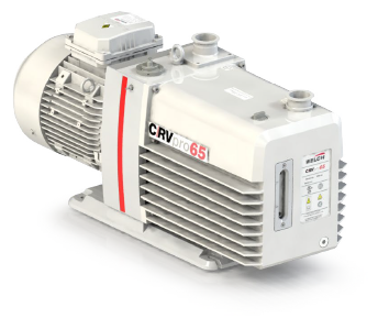
The Edwards “RV” (simply meaning Rotary Vane) laboratory sized oil-sealed rotary vane vacuum pumps (Fig. 1) have been in the market since 1993. They have a very unique design with no equal. This article will attempt to show the reasons for its design and introduction and then explain the features of the vacuum pump that make it one of the best small vacuum pumps available today. This is not an official Edwards account, although the engineering related content is based on Edwards information, it contains my personal knowledge, experience and understanding from working with these pumps for many years.
Fig. 1: The “RV” Rotary Vane vacuum pump.
The earlier Edwards EM vacuum pumps
As I mentioned in a previous article, European vacuum pump companies were the first to develop direct drive oil sealed rotary vane vacuum pumps. These are the pumps capable of reducing the pressure to around a two thousandth part of one Torr total pressure (2 x 10⁻³ Torr or 2 microns) as shown in their catalogs.
These direct drive vacuum pumps from the original companies such as Leybold, Alcatel, Edwards, Pfeiffer, and others dominate this laboratory size vacuum pump market, the only US manufacturer being Kinney.
Edwards introduced their second range of direct drive pumps called “EM” (Edwards Mechanical) in the late 70s as far as I can tell. (At that time I did not work for Edwards but I have a number of documents that I use for reference.) The range started with models EM2 (1.5 cfm), EM5 (3.5 cfm), EM8 (6 cfm) and EM12 (9 cfm) classed as laboratory size and included 6 larger sizes up to about 190 cfm.
This range of pumps was available for many years and the larger sizes are still current today, close to 40 years later. However, in the early 90s, a new vacuum application came along that required the laboratory sized vacuum pumps to be redesigned.
Gel Drying
The laboratory application that caused a problem for the vacuum pump was one that generates lots of condensable vapor. The full name of the process is protein gel electrophoresis, where a sheet of material is stained by the process and then has to be dried to fix it. The liquid involved is a mixture of water, methanol, glycerol and acetic acid.
At that time the drying was carried out under vacuum with the vapors ending up in the vacuum pump. It was found that the existing Edwards EM series pumps did not have enough gas ballast flow to handle the amount of condensable vapors entering the pump. That resulted in the pump oil being contaminated with liquid droplets which adversely affected the vacuum and meant the oil had to be changed frequently. In technical specifications for these pumps, the water vapor pumping capacity is shown in kilograms per hour (kg.h-1)
Because this process was used in many labs, the inadequate vapor handling capacity was a problem that needed to be fixed; hence the RV range of laboratory vacuum pumps was developed.
Requirements of a new Lab Sized Vacuum Pump design
In addition to the need for increased vapor handling capacity, there were several other reasons to redesign this type of vacuum pump.
Competition in the marketplace made it important to reduce manufacturing costs to stay competitive with prices. And, as the vacuum companies became more global, mostly the US market in the 80s, the company had to increase the number of employees in the US as the company grew quickly. These employees were sales, marketing, and service supported by the order department, accounting and warehouse teams. They could only be afforded with a combination of increased sales and manufacturing cost reductions.
The laboratory vacuum pump market is a high volume business and cost savings would be multiplied with additional sales. The earlier change in design from vee belt driven pumps to direct driven pumps was also to reduce the manufacturing cost, but the design of the pump cartridge inside the oil box remained very similar. The RV design was completely new.
Fig. 2: The Mode Selector valve.
Other reasons for the redesign were to improve a few features of the EM design pumps. These were small things separately but caused frustration when added together.
1) The gas ballast valve would unscrew and come off in your hand. There was no stop on it.
2) The main components of the pump stator were machined from iron castings and required a number of different steps to manufacture them.
3) The oil circuit passageways drilled into the pump castings were relatively small bore and in some applications would become blocked by contaminants or degraded oil which was difficult to remove.
4) The applications for this type of vacuum pump required a single stage and two stage versions to be available. Typically the single stage versions are used for higher pressure industrial applications and the two-stage versions for lower pressure scientific applications. The EM lab sized range included six models.
5) Pump vanes, or blades, were manufactured from a resin reinforced with asbestos fibers. Even though these items were wet with oil and could not release fibers of asbestos, there was pressure to replace the material.
6) Shipping small EM bare shaft pumps (no motor) to the US, adding 115-volt motors and retesting the pump was inefficient.
Features of the RV vacuum pump
The following is a list of the main features of the RV pump, followed by comments on each feature.
a) The first “Dual mode” vacuum pump
Vacuum pumps are available in one stage and two stage versions. The two-stage vacuum pump, used for most laboratory applications, attains a slightly lower pressure (higher vacuum) than a one stage vacuum pump. Although the ultimate vacuum of this type of pump is controlled by the vapor pressure of the oil another limiting factor is the amount of air bubbles mixed in the oil. If you look at the oil in the oil box through the oil level sight glass, when the pump is running, you can see small bubbles of gas entrained in the oil. When the gassy oil enters the lower pressure area of the pump the air bubbles are released from the oil. The oil degasses.
A one stage pump interior is lubricated with undegassed oil straight from the oil box. That gas is released once the oil enters the low-pressure volume and limits the vacuum that can be produced. In a two-stage pump the oil is initially fed to the second stage, where it degasses, and then it is drawn into the first stage (by the pressure difference) where the pure degassed oil allows the ultimate pressure to be a little lower.
In the RV vacuum pump, there is a small valve mounted on one side called the “Mode Selector” (Fig. 2). This valve is closed when the pump is shipped from the factory. The open and closed positions are shown pictorially by a few small oil drops on the right (closed) and by a few larger oil drops on the left (open). The valve knob is mounted behind a hole in the side plate. It opens in a counterclockwise direction, just like most valves, and stops when the outside lip of the knob reaches the side plate.
In the closed position, the vacuum pump acts as a two-stage vacuum pump and delivers the lowest pressure as specified. This is the setting for most laboratory applications.
If the vacuum pump is required to run at a higher inlet pressure for an extended period of time, for example above 10 Torr, it is possible for the first stage of the pump to become starved of lubricant, oil. Oil is constantly circulating around the vacuum pump. The oil pump supplies the oil and the oil is blown out through the exhaust valves back into the oil box. At a high inlet pressure less oil is being delivered into the first stage and it is losing more oil, blown out in the gas stream. If the first stage doesn’t receive enough oil some metal to metal contact may occur which could lead to the pump seizing up. To prevent this oil starvation the vacuum pump is set to run with the Mode Selector switch open. This allows additional oil directly from the oil box, undegassed oil, to enter the first stage and provide sufficient oil for lubrication.
Fig. 3: RV pump “cartridge” (with dimples).
The Mode Selector switch allows the four sizes of RV vacuum pump to run as either a two-stage pump or a one stage pump. Eight models in four pumps. No one else has this feature.
b) Pump stator components machined from round bar stock
As stated earlier the previous EM range of pumps was manufactured from machined iron castings. The RV pump cartridge sections (Fig. 3) are machined from bar stock using CNC workstations. I’m not an efficiency expert on manufacturing costs, but it appears that this is a much more efficient way to make pump components than molding castings a few at a time and then machining each one. The stator sections bolt together as the pump cartridge is assembled, and the bolt holes are offset from the center line so that assembly is only possible in the correct orientation.
c) Dimples machined on stator sections
When this pump range was first introduced the pump cartridge was assembled by a robotic machine. The robot looked similar to those used in the automotive industry to do many repetitive tasks. The robot “hand” had three fingers, so each stator section had three dimples machined around the outside (Fig. 3) to allow the robot to pick it up.
The idea behind the robot was to make the pump assembly as consistent as possible to maximize the number of pumps that would pass final tests the first time. Previous manufacturing practice was for two or three assemblers to work on a batch of pumps at a time, perhaps twenty or thirty pumps. Once assembled, they would go to the test department where they would be fitted with a test motor, be run in and tested for correct performance. It was thought that robotic assembly would reduce the amount of rework on pumps that didn’t pass the testing.
The robot did a good job with the assembly but had to have bins of parts available for it to use and these bins needed to be refilled constantly by humans. There wasn’t much cost saving on the labor side. It also took up a lot of floor space and I don’t think it was as cost-effective as initially thought. Later on, the company returned to batch assembly of the RV pumps but made one change. The team that assembled the batch of pumps was made responsible for testing them. This gave them an incentive to ensure the pumps were assembled correctly the first time.
d) Universal motor
A big cost reduction was seen when the dual voltage motors (Fig. 1 right-hand side) were introduced. Rather than using a conventional C face motor and having a locally supplied motor added to the pump in whatever country it was shipped to, the universal motor allowed it to be assembled and tested at the factory. The motor is dual voltage and can be changed by turning the on-off switch around inside the top cover. This motor also has a separate power cord with it as power plugs are different from country to country. The universal type of motor is now used by all major direct drive vacuum pump manufacturers.
e) Improved vapor handling capacity
The gas ballast valve (Fig. 3) on the RV pump has three setting, Off (closed), Position l and Position ll. This valve turns through the three settings and will not come loose in the operators’ hand.
The gas flow in Position l is about equal to that of the EM pumps. The gas flow in Position ll is approximately twice that of the previous pumps. The additional gas flow allows the pump to pass more condensable vapor through it without it condensing.
On checking the vapor handling capacity I noticed that it is higher for pumps using single phase motors. An Edwards contact confirmed that single phase motors produce more heat which is deliberately used to make the pump run hotter. The higher running temperature also helps increase the vapor handling capacity. Three phase motors, being more efficient, give off less heat and therefore the vapor handling capacity is lower, but still substantially higher than the old pumps.
f) Oil circuit improvements
The major change in the RV oil circuit is that pump oil is used to seal the sections of the stator. This is another first, not seen in any other design. Each stator section is machined around its periphery so that there is an oilway allowing the oil to circulate and effectively seal each section where the sections connect. This eliminates the need for gasket seals, O-ring seals or the liquid sealant often used on machined surfaces that need to be leak tight. (It also made life easier for the assembly robot!) In addition, the oil pressure developed by the oil pump was increased, other oil passageways around the pump were made larger and the overall oil flow was increased.
A small change was made to the oil pump blade to give it a rectangular cross-section. This ensures that it can only be installed in the correct way. The previous EM oil blade had a square cross-section and because it had rounded ends could be installed incorrectly which would cause it to jam and the pump to fail.
g) Hydraulic inlet valve
Part of the improved oil circuit is the hydraulically operated inlet shut-off valve. This makes a positive barrier between the pump interior and the vacuum system in the event that the pump stops or the oil pressure drops. Usually, the only reason for the oil pressure to drop would be that the pump has stopped; either switched off or due to a power failure.
In the EM pumps the anti-suckback valve (to prevent oil being “sucked back” towards the pump inlet and the vacuum system if the pump stopped under vacuum) was a spring-loaded distributor valve mounted on top of the pump cartridge. However, the pump inlet would still be open which could allow air and perhaps oil vapor to leak back to the customer’s system. Now the RV inlet to the vacuum pump is closed automatically if the pump stops or the oil pressure drops for some reason.
The RV inlet valve is opened by the oil acting on a piston and moving the inlet downwards against a heavy spring. The oil flow to the hydraulic piston is controlled so that the valve only opens after the pump has been running for several seconds. This allows the pump interior to be re-evacuated before it is opened to the vacuum system. This prevents gas bursts and possible contamination into the vacuum system. When the pump is switched off, a dump valve assembly in the inlet valve oil circuit reduces the oil pressure almost instantly allowing the spring loaded inlet valve to isolate the pump from the system very quickly.
Fig. 4 RV internal parts.
Most other lab sized direct drive vacuum pumps now have an inlet valve controlled by the oil pressure, but I do not know if they include the “slow to open and quick to close” feature.
h) Separate high vacuum and low vacuum rotors
A design feature of small lab sized direct drive vacuum pumps is that there are no ball bearings on the rotors. Because the pumps are only moving small quantities of air or gas, there are no heavy perpendicular or axial forces on the rotor. This allows the bearing to consist of only an oil film separating the stationary bore in the stator from the rotating shaft of the rotor. (It is another reason that the vacuum pump oil should be clean and not contaminated.) To make these oil film bearings work it is important to keep the weight of the rotor below a certain limit. In the RV pump, the rotors are separate items and they are coupled together, so that one turns the other, using small Oldham couplings that also “float” on the oil (Fig 4.).
i) Shaft sleeve and spacer with oil seal
In the previous pump design, the oil pump was right next to the drive shaft of the pump. The drive shaft has to have an oil seal on it to prevent pump oil from leaking out. By putting the oil pump there a second seal was needed on the inside allowing the oil pressure to be built up between the seals. Two things happen with shaft seals; one, the elastomer eventually hardens and or wears until it leaks and two, it can wear a slight groove in the shaft. It is recommended that shaft seals be changed about every two years if a pump is used frequently. If a groove is worn into the shaft it may be more prone to leak even if a new seal is fitted because the new seal is sealing in the groove. Replacing the shaft, which is part of the rotor assembly, is costly.
In the RV pump, the oil pump is located at the end of the cartridge furthest away from the drive shaft that is connected by a coupling to the motor. That reduces the oil pressure at the shaft seal location, but the seal still needs to be lubricated and two oil seals are required. The outer shaft seal prevents oil from leaking out of the pump and the inner oil seal contains the oil in that area for constant lubrication.
The RV design has added a shaft sleeve to the shaft and both shaft seals are located along the sleeve. If either seal damages the sleeve (wears a groove) it is less costly to replace the sleeve than the complete shaft and rotor assembly. In addition, the replacement seal kit includes a spacer that can be inserted into the outer bearing housing when the seal is replaced. If the sleeve is worn under the old seal, the spacer moves the replacement seal to a new location on the sleeve. This again gives the sleeve a longer life.
Fig. 5 New RV gaskets.
j) Nonstandard gaskets
This pump uses four nontraditional gaskets (Fig. 5) to seal several of the major pump components and prevent oil leaks. Traditional gaskets are made from sheets of thin cork material and have been in use for many years. The new design uses a bead of silicone rubber bonded to a Mylar backing material. These gaskets were not too successful in the beginning because the sealing material separated from the substrate. Changes were made to the materials used and these gaskets are now much more reliable.
k) Same basic repair parts for all sizes
All four sizes of the RV vacuum pump use the same Clean and Overhaul Kit. This kit contains all the replaceable gaskets, seals, springs, exhaust valves and o-rings required for a pump service. The blades or vanes are supplied as a separate kit as they are different for each size of pump and don’t need to be changed as frequently as the parts such as shaft seals.
l) Blade material changed
The blade or vane material is now a molded polymer that has low thermal expansion. They are molded with a groove in one side and that groove should face the forward motion of the blade. This allows the groove to pick up oil for lubrication. One old feature of the blades is still present though not needed now, at least in the blades I have seen recently. One corner of the blade has a bevel on it (Fig. 4). This bevel was to help the robot locate the blade in the blade slot and then insert it.
m) Oil box design
Several changes were made to the oil box. An additional oil fill plug was added to the top of the box. This was to allow a gravity drain accessory to be added allowing oil from the mist filter to return to the oil reservoir. The top of the oil box now has a raised edge that captures any small oil spills when refilling the pump. The oil level sight glass was made a separate part that can be removed for cleaning. Sight glasses on the old EM pumps could not be cleaned if they became stained from contaminants in the oil. Lastly, the oil drain was made larger which makes draining the oil a little faster.
o) The last improvement was in the baseplate.
EM pump baseplates were stamped steel which were prone to bending if the pump was put down too heavily. The RV baseplates are cast aluminum which is more resistant to damage. It also incorporates a “well” under the pump which will catch oil drips if there is an oil leak.
Final Comments
This innovative design which Edwards is well known for if you are familiar with their semiconductor dry pump designs, has worked well for over twenty years and continues to be a popular product for both scientific and smaller industrial vacuum applications.
It indicates to me that products made by companies that invest in their own research and development are better “value for money” in the long run, even if the products cost a bit more.
When these pumps were introduced in North America it became apparent that the existing “standard” high vacuum oil was not suitable for the hotter running RV pump. Edwards worked with a major oil company to produce higher quality oil they call Ultragrade 19. This oil has a higher temperature rating, additives to prevent corrosion and a lower sulfur content to resist breakdown. This oil, or an equivalent should always be used in the RV pump.
Copyright Howard Tring, Tring Enterprises LLC Vacuum & Low-Pressure Consulting.
Comments
Be the first to comment...