
You have no items in your shopping cart
An Introduction To Vacuum Pumps
- Posted on
- Posted in Buyers Guides, Vacuum Pump
- 0
An exploration of various pump types and their uses
When designing or operating a vacuum system, it is critical to understand the function of the vacuum pumps. We will review the most common types of vacuum pumps, their principles of operation and where in the system they are used.
Pump Categories (by Operating Pressure)
Vacuum pumps are categorized by their operating pressure range and as such are classified as primary pumps, booster pumps or secondary pumps. Within each pressure range are several different pump types, each employing a different technology, and each with some unique advantages in regard to pressure capacity, flow rate, cost and maintenance requirements.
Regardless of their design, the basic principle of operation is the same. The vacuum pump functions by removing the molecules of air and other gases from the vacuum chamber (or from the outlet side of a higher vacuum pump if connected in series). While the pressure in the chamber is reduced, removing additional molecules becomes exponentially harder to remove. As a result, an industrial vacuum system (Fig. 1) must be able to operate over a portion of an extraordinarily large pressure range, typically varying from 1 to 10-6 Torr of pressure. In research and scientific applications, this is extended to 10-9 Torr or lower. In order to accomplish this, several different styles of pumps are used in a typical system, each covering a portion of the pressure range, and operating in series at times.
Vacuum systems are placed into the following broad-based grouping of pressure ranges:
- Rough/Low Vacuum: > Atmosphere to 1 Torr
- Medium Vacuum: 1 Torr to 10-3 Torr
- High Vacuum: 10-3 Torr to 10-7 Torr
- Ultra-High Vacuum: 10-7 Torr to 10-11 Torr
- Extreme High Vacuum: < 10-11 Torr
The different types of pumps for these vacuum ranges can then be divided into the following:
- Primary (Backing) Pumps: Rough and low vacuum pressure ranges.
- Booster Pumps: Rough and low vacuum pressure ranges.
- Secondary (High Vacuum) Pumps: High, very high and ultra-high vacuum pressure ranges.
Figure 1 – Typical industrial vacuum system (Illustration Courtesy of Edwards)
Terminology
The two technologies used by vacuum pumps are gas transfer and gas capture (Fig. 2).
Transfer pumps operate by transferring the gas molecules by either momentum exchange (kinetic action) or positive displacement. The same number of gas molecules are discharged from the pump as enter it and the gas is slightly above atmospheric pressure when expelled. The ratio of the exhaust pressure (outlet) to the lowest pressure obtained (inlet) is referred to as the compression ratio.
Kinetic transfer pumps work on the principle of momentum transfer, directing gas towards the pump outlet to provide increased probability of a molecule moving towards the outlet using high-speed blades or introduced vapor. Kinetic pumps do not typically have sealed volumes but can achieve high compression ratios at low pressures.
Positive displacement transfer pumps work by mechanically trapping a volume of gas and moving it through the pump. They are often designed in multiple stages on a common drive shaft. The isolated volume is compressed to a smaller volume at a higher pressure, and finally, the compressed gas is expelled to atmosphere (or to the next pump). It is common for two transfer pumps to be used in series to provide a higher vacuum and flow rate. For example, a turbomolecular (Kinetic) pump can be purchased in series with a scroll (Positive displacement) pump as a packaged system.
Figure 2 – Types of vacuum pumps (Illustration Courtesy of Edwards)
Capture pumps operate by capturing the gas molecules on surfaces within the vacuum system. Capture pumps operate at lower flow rates than transfer pumps but can provide ultra-high vacuum, down to 10-12 Torr, and generate an oil-free vacuum. Capture pumps operate using cryogenic condensation, ionic reaction, or chemical reaction and have no moving parts.
Types of Pumps – An Overview
The different pump technologies are considered either wet or dry type pumps, depending on whether or not the gas is exposed to oil or water during the pumping process. Wet pump designs use oil or water for lubrication and/or sealing and this fluid can contaminate the swept (pumped) gas. Dry pumps have no fluid in the swept volume and rely on tight clearances between the rotating and static parts of the pump, dry polymer (PTFE) seals, or a diaphragm to separate the pumping mechanism from the swept gas. Although dry pumps may use oil or grease in the pump gears and bearings, it is sealed from the swept gas. Dry pumps reduce the risk of system contamination and oil disposal compared to wet pumps. Vacuum systems are not easily converted from wet to dry by simply changing the pump from a wet to a dry style. The chamber and piping can be contaminated by the wet pump and must be thoroughly cleaned or replaced, otherwise, they will contaminate the gas during future operation.
Following is an introduction to the most commonly used vacuum pump types by function.
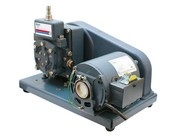
In the rotary vane pump, the gas enters the inlet port and is trapped by an eccentrically mounted rotor which compresses the gas and transfers it to the exhaust valve (Fig. 3). The valve is spring-loaded and allows the gas to discharge when atmospheric pressure is exceeded. Oil is used to seal and cool the vanes. The pressure achievable with a rotary pump is determined by the number of stages used and their tolerances. A two-stage design can provide a pressure of 1×10⁻³ mbar. It has a pumping speed of 0.7 to 275 m3/h (0.4 to 162 ft3/min).
Figure 3 – Cross-section of a typical wet pump (Illustration Courtesy of Edwards)
Liquid Ring Pump (Wet, Positive Displacement)
The liquid ring pump (Fig. 4) compresses the gas by rotating a vaned impeller located eccentrically within the pump housing. Liquid is fed into the pump and, by centrifugal acceleration, forms a moving cylindrical ring against the inside of the casing. This liquid ring creates a series of seals in the space between the impeller vanes, which form compression chambers. The eccentricity between the impeller’s axis of rotation and the pump housing results in a cyclic variation of the volume enclosed by the vanes and the ring, which compresses the gas and discharges it through a port in the end of the housing. This pump has a simple, robust design as the shaft and impeller are the only moving parts. It is very tolerant of process upsets and features a large capacity range. It can provide a pressure of 30 mbar using 15°C (59° F) water, and lower pressures are possible with other liquids. It has a pumping speed range of 25 to 30,000 m3/h (15 to 17,700 ft3/min).
Figure 4 – Cross-section of a typical ring pump (Illustration Courtesy of Edwards)
Diaphram Pump (Dry, Positive Displacement)
A diaphragm is rapidly flexed by a rod riding on a cam rotated by a motor, causing gas transfer in one valve and out the other. It is compact and low maintenance. The lifetime of the diaphragms and valves is typically over 10,000 operating hours. The diaphragm pump (Fig. 5) is used for backing small compound turbo-molecular pumps in clean, high vacuum applications. It is a small capacity pump widely used in R & D labs for sample preparation. A typical ultimate pressure of 5 x 10⁻⁸ mbar can be achieved when using the diaphragm pump to back a compound turbo-molecular pump. It has a pumping speed range of 0.6 to 10 m3/h (0.35 to 5.9 ft3/min).
Figure 5 – Cross section of a typical diaphram pump (Illustration Courtesy of Edwards)
Scroll Pump (Dry, Positive Displacement)
The scroll pump (Fig. 6) uses two scrolls that do not rotate, but where the inner one orbits and traps a volume of gas and compresses it in an ever decreasing volume; compressing it until it reaches a minimum volume and maximum pressure at the spirals’ center, where the outlet is located. A spiral polymer (PTFE) tip seal provides axial sealing between the two scrolls without the use of a lubricant in the swept gas stream. A typical ultimate pressure of 1 x 10⁻² mbar can be achieved. It has a pumping speed range of 5.0 to 46 m3/h (3.0 to 27 ft3/min).
Figure 6 – Cross section of a typical scroll pump (Illustration Courtesy of Edwards)
BOOSTER PUMPS
Roots Pump (Dry, Positive Displacement)
The Roots pump (Fig. 7) is primarily used as a vacuum booster and is designed to remove large volumes of gas. Two lobes mesh without touching and counter-rotate to continuously transfer the gas in one direction through the pump. It boosts the performance of a primary/backing pump, increasing the pumping speed by approximately 7:1 and improves ultimate pressure by approximately 10:1. Roots pumps can have two or more lobes. A typical ultimate pressure of < 10-3 Torr can be achieved (in combination with primary pumps). It can achieve pumping speeds in the order of 100,000 m3/h (58,860 ft3/min).
Figure 7 – Cross-section of a typical Roots pump (Illustration Courtesy of Edwards)
Claw Pump (Dry, Positive Displacement)
The claw pump (Fig. 8) features two counter-rotating claws and operates similarly to the Roots pump, except that the gas is transferred axially, rather than top-to-bottom. It is frequently used in combination with a Roots pump, which is a Roots-claw primary pump combination in which there are a series of Roots and claw stages on a common shaft. It is designed for harsh industrial environments and provides a high flow rate. A typical ultimate pressure of 1 x 10⁻³ mbar can be achieved. It has a pumping speed range of 100 to 800 m3/h (59 to 472 ft3/min).
Figure 82 – Cross-section of a typical claw pump (Illustration Courtesy of Edwards)
Screw Pump (Dry, Positive Displacement)
The screw pump (Fig. 9) utilizes two rotating screws, one left-handed and one right-handed, that mesh without touching. The rotation transfers the gas from one end to the other. The screws are designed so the space between them becomes reduced as the gas passes along, and it becomes compressed, causing a reduced pressure at the entrance end. This pump features a high throughput capacity, good liquid handling, and tolerates dust and harsh environments. A typical ultimate pressure of approximately 1 x 10⁻² Torr can be achieved. It has a pumping speed range of up to 750 m3/h (440 ft3/min).
Figure 9 – Cross section of a typical screw pump (Illustration Courtesy of Edwards
SECONDARY PUMPS
Turbomolecular Pumps (Dry, Kinetic Transfer)
Turbomolecular pumps (Fig. 9) work by transferring kinetic energy to gas molecules using high speed rotating, angled blades that propel the gas at high speeds: the blade tip speed is typically 250 -300 m/s (670 miles/hr.) By transferring momentum from the rotating blades to the gas, they provide a greater probability of molecules moving towards the outlet. They provide low pressures and have low transfer rates. A typical ultimate pressure of less than 7.5 x 10⁻¹¹ Torr can be achieved. It has a pumping speed range of 50 – 5000 l/s. The bladed pumping stages are often combined with drag stages that enable turbomolecular pumps to exhaust to higher pressures (> 1 Torr).

Figure 9 – Cross-section of a typical turbomolecular pump (Illustration Courtesy of Edwards)
Vapor Diffusion Pumps (Wet, Kinetic Transfer)
Vapor diffusion pumps (Fig. 10) transfer kinetic energy to gas molecules using a high velocity heated oil stream that “drags” the gas from the inlet to the outlet, providing a reduced pressure at the inlet. These pumps feature an older technology, largely superseded by dry turbomolecular pumps. They have no moving parts and provide high reliability at a low cost. A typical ultimate pressure of less than 7.5 x 10⁻¹¹ Torr can be achieved. It has a pumping speed range of 10 – 50,000 l/s.
Figure 10 – Cross section of a typical diffusion pump (Illustration Courtesy of Edwards)
Cryopump (Dry, Entrapment)
The Cryopump (Fig. 11) operates by capturing and storing gases and vapors, rather than transferring them through the pump. They use cryogenic technology to freeze or trap the gas to a very cold surface (cryocondensation or cryosorption) at 10°K to 20°K (minus 260°C). These pumps are very effective but have limited gas storage capacity. Collected gases/vapours must periodically be removed from the pump by heating the surface and pumping it away through another vacuum pump (known as regeneration). Cryopumps require a refrigeration compressor to cool the surfaces. These pumps can achieve a pressure of 7.5 x 10⁻¹⁰ Torr and have a pumping speed range of 1200 to 4200 l/s.

Figure 11 – Cross-section of a typical Cryopump (Illustration Courtesy of Edwards)
Sputter Ion Pumps (Dry, Entrapment)
The sputter ion pump (Fig. 12) traps gases using the principles of gettering (whereby chemically active materials combine with gases to remove them) and ionization (gas molecules are made electrically conductive and captured). A high magnetic field combined with a high voltage (4 to 7kV), creates a cloud of electrons-positive ions (plasma) which are deposited onto a titanium cathode and sometimes a secondary additional cathode composed of tantalum. The cathode captures the gases, resulting in a getter film. This phenomenon is referred to as sputtering. The cathode must be periodically replaced. These pumps have no moving parts, are low maintenance, and can achieve a pressure as low as 7.5 x 10⁻¹² Torr. They have a maximum pumping of 1000 l/s.
Figure 123 – Cross section of a typical ion pump
In Summary…
The various types of vacuum pumps have been briefly described here but a more detailed discussion of each is needed to fully understand the advantages and limitations of each technology.
Vacuum pumps are one of, if not the most important set of components supplied on vacuum furnaces. The processes we run and the quality we achieve is a function of how these systems perform.
References
1. Herring, Daniel, Vacuum Heat Treatment, Volume I, BNP Media, 2012.
2. Felixstowe Docers (http://felixstowedocker.blogspot.com/2015/03/case-study-cavotec-moormaster.html).
3. Philip Hoffman (www.philiphoffman.net).
Comments
Be the first to comment...