
You have no items in your shopping cart
Roots Blowers (aka Booster Pumps)
- Posted on
- Posted in Vacuum Pump
- 0
A brief look into what a booster pump is and when are they needed
Booster pumps (aka Roots blowers or intermediate stage vacuum pumps) fall into the class of dry, gas transfer pumps. As a dry pump, they do not introduce oil or water into the pumped gas stream. Gas transfer is accomplished by mechanically means, that is the transfer of pumped gas molecules, rather than their collection, as with, for example, cryogenic or turbomolecular pumps.
The words “Roots blower” are synonymous with these pumps and the reason they are also commonly referred to as booster pumps is that they are mounted at the inlet of a primary/backing pump (such as a rotary vane, claw pump, or screw pump). They “boost” the performance of the primary pump improving pumpdown speed (much as a relay race in which the baton is passed from one runner to the next). The combination of Root blower and primary pump provides roughly a seven-fold increase in pumping speed and a ten-fold increase in pressure, in comparison to a primary pump alone.
Introduction
When used in a high or ultra-high vacuum system, the Roots blower is located between the primary pump and a diffusion (or other style) high vacuum pump. In this arrangement, a bypass is incorporated whereby the Roots pump and primary pumps operate with the high vacuum pump in bypass mode during the initial pump down (roughing) stage. This takes advantage of the high flow rate (“speed”) available with the Roots/primary combination. After roughing is complete and the system reaches medium to high vacuum, the bypass is closed and the primary, Roots blower, and diffusion pumps operate in series to achieve a high vacuum at a reduced flow rate.
Due to the prevalence of Roots boosters in industrial vacuum systems, it is important for system designers and operators to have a sound understanding of how they function and how to maintain them. Here we cover pump principle of operation, multi-stage pumps, temperature effects, gas cooling, and maintenance.
Principle of Operation
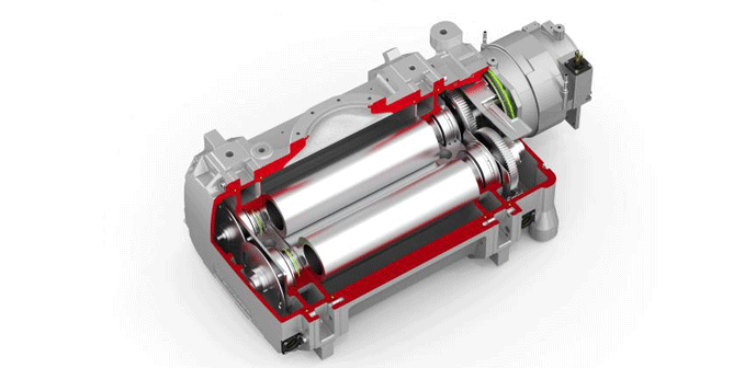
The Roots blower utilizes two rotors, each featuring two (Fig. 1) or three lobes which function as rotary pistons. The rotors mesh without touching and counter-rotate to continuously transfer gas in one direction through the pump. The rotation is synchronized through the use of a precision gear drive arrangement, with each rotor mounted to separate, parallel shafts. The rotors are precision engineered to maintain a very small clearance between each other, and between the rotors and the pump housing. This tight clearance, along with the viscosity of the gas and the friction between the gas and the rotors moving at high speeds, causes resistance to the backflow of gas, creating a non-contact, dry seal.
The ultimate achievable vacuum is limited by gas backflow across these dry sealing surfaces. The other limiting factor, not only in Roots blowers but other dry pumps as well, is a boundary layer of gas that forms on the rotors and the housing. During the compression phase of each rotation, the gas momentarily adheres to these surfaces, before releasing during the suction phase. The thickness of the traveling gas layer depends on the clearances between the rotors, and between the rotors and the housing.
 |
| Figure 1 | Cutaway view of a single-stage, two lobe Roots blower (courtesy of Edwards Vacuum) |
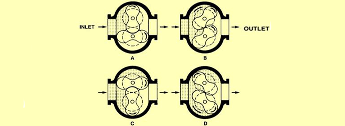
Gas transfer in a Roots blower can be thought of as occurring in phases (Fig. 2). In the initial or “A” phase of operation, the pump chamber is opened by the rotation of the pistons. In the next or “B” phase, additional gas is drawn into the pumping chamber as the pistons continue to rotate. In the “C” phase, the upper chamber is sealed off against both the inlet flange and the pressure flange, isolating a pocket of gas and transferring it towards the outlet. As rotation continues in the “D” phase, the outlet is opened and the gas is discharged.
 |
| Figure 2 | Phases of operation of a Roots blower (courtesy of Edwards Vacuum) |
Multiple Stage Designs
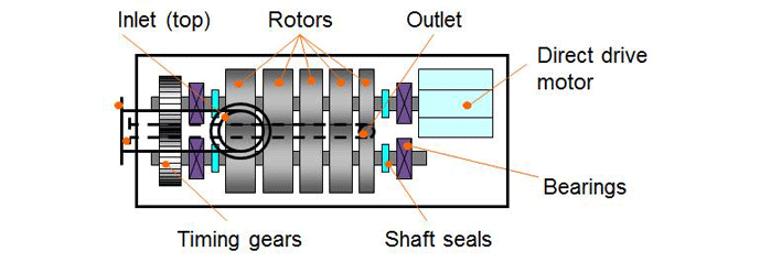
To achieve improved pumping speed and higher vacuum, more than one booster stage (rotor) may be used (Fig. 3). When two boosters are operated in parallel (Fig. 4), for example, a one-decade improvement in ultimate vacuum is possible, and the pumping speed can be increased by more than 10 times at pressures in the range of 7.5 x 10⁻³ Torr (10-2 mbar) to 7.5 Torr (10 mbar). This improvement in pumping speed is more modest at higher pressures. When boosters are operated in series, the enhancement in speed is less than with parallel operation, but the improvement in ultimate vacuum is more significant.
 |
| Figure 3 | Example of a five-stage Roots blower (courtesy of Edwards Vacuum) |
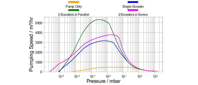 |
| Figure 4 | Efficiency improvement from two Roots blower operating in parallel and in series (courtesy of Edwards Vacuum) |
Temperature Effects
Due to the tight clearances between the rotors, and between the rotors and the housing, the pump temperature affects the operating characteristics. This is due to the thermal expansion of the rotors. When the pump is in operation, considerable heat is generated, causing the rotors to heat up more than the housing, which can more easily dissipate its heat. The difference in temperature between the rotors and the housing causes a proportional difference in thermal expansion whereby the rotors grow more than the housing, and reduce the clearance between the rotors and the housing. This improves the pump’s ability to seal against backflow.
The smallest clearances and thus the lowest backflows are attained at inlet pressures of approximately 7.5 x 10⁻¹ Torr (1 mbar) to 7.5 Torr (10 mbar). In this range, the pump can maintain a pressure ratio (output pressure/input pressure) of up to 20:1. At higher inlet pressures, the gas is heavier, resulting in more power required for gas flow and in higher rotor temperatures, which in turn decrease the above-mentioned clearances. At inlet pressures greater than 75 Torr (100 mbar), there is a risk of contact between the rotors and housing, causing pump failure, unless gas cooling is employed.
Gas Cooling
When it is required that a roots pump operate at inlet pressures of 75 Torr (100 mbar) to 750 Torr (1000 mbar), gas cooling is necessary. After the gas leaves the pump’s outlet flange (6), it is passed through a heat exchanger (7), and then introduced at the middle of the pump (4) during the suction phase of rotor (1) & (2) rotation. This cools the pump, enabling it to compress against higher inlet pressures (5), up to atmospheric pressure without thermal failure. The flow of cooled gas is controlled by the rotors, which eliminates the need for any additional valves.
Maintenance
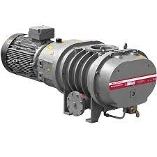
Roots blowers (Fig. 5) have the reputation of being virtually indestructible and run for years seemingly unattended while the primary (mechanical) and high vacuum (diffusion pumps seem to receive all the attention. While they need little day-to-day maintenance, monitoring of the oil level in the pump is required. The main function of these booster pumps is to improve pumpdown rates and ultimate vacuum levels.
 |
| Figure 5 | Typical two-stage Roots blower (courtesy of Edwards Vacuum) |
Contained within the pump housing are rotary pistons and timing gears in a gear case fitted with troughs, which control the amount of oil, supplied to the gear teeth. A typical procedure is to fill the gear case with the appropriate grade of oil until it overflows from the oil level/filler hole. Allow the excess oil to drain before inserting the oil level filler plug. This must be done when the blower is not in operation. Overfilling must be avoided, as this will cause the gears to run hot, resulting in damage. The oil level should be checked weekly or every 100 working hours. Drain and refill the gear case to the correct level every six to twelve months depending upon the condition of the oil. When there are considerable seasonal temperature variations, it may be necessary to change the grade of oil at certain times during the year.
The oil used should be suitable (i.e. have the proper viscosity) for the minimum ambient temperature (cold starting) and for the highest oil temperature reached on maximum load (Table 33.6.1). The recommended oil for most booster pumps is straight mineral oil, which may contain anti-wear, anti-rust, anti-foam, and anti-oxidant additives. The oil should not contain either an extreme pressure additive or additives that emulsify. The oil should have a viscosity of not more than 2,500 centistokes at the minimum ambient temperature (cold starting) and not less than 30 centistokes for the highest oil temperature reached on maximum load. When there are considerable seasonal variations in ambient temperatures, summer and winter grades of oil will be required.
 |
| Table 1 | Oil viscosity selection chart2 |
Typical maintenance activities include the following:
1. Timing gears. Wear should be negligible over a period of years of normal service. Gear teeth are provided with the correct amount of backlash, and a reasonable amount of tooth wear can normally be accommodated without permitting contact between lobes of the two impellers. A high oil level in the gearbox will cause churning and excessive oil heating, indicated by unusually high temperatures in the bottom of the sump. If the operation is continued under this condition, gears will heat and the teeth can be affected with rapid wear, which will lead to impeller lobe contact or unit seizure.
2. Shaft bearings. These bearings are critical in the service life of the booster. Gradual wear may allow a shaft position to change slightly until rubbing develops between the impeller and cylinder or head plate. This will cause spot heating detected by feeling these surfaces. Sudden bearing failure is usually more serious. Since the impeller shaft assembly is no longer supported and properly located, extensive general damage to casing and gears is likely to occur immediately after the bearing fails.
3. Driveshaft seal assembly. This assembly consists of two individual lip-type seals submerged in oil and located in the drive end cover, which should be considered as expendable. It should be replaced as an assembly whenever oil leakage through the inboard member becomes excessive as indicated by a rise in oil level at the sight gauge. Leakage through the outboard member is not likely to be excessive unless that seal or its shaft-bearing surface is damaged. Shaft smoothness and freedom from scratches have a considerable effect on the performance of this type of seal. Operating problems may also result from causes other than parts damage. Since clearances are only a few thousandths of an inch, interferences and rubs can be caused by shifts in the mounting or changes in pipe supports.
4. Casing issues. Foreign materials entering the casing will also cause trouble. If this type of problem is experienced, and the casing is found to be clean internally, try removing strains. Disconnect piping and loosen mounting bolts, and reset the leveling and drive alignment. After tightening the mounting, make sure all piping meets unit connections accurately and squarely before reconnecting.
Summary
The need to add a booster pump into the vacuum system is somewhat dependent on the style of vacuum furnace (batch or continuous) under discussion. However, the benefits of achieving lower vacuum levels and, when necessary, a faster pumpdown time from initial conditions make the addition of this rugged pump a logical choice.
References
1. Herring, Daniel H., Vacuum Heat Treatment, BNP Media, 2012.
2. Blower Maintenance Manual DRI-114-0502, Dresser Roots
3. Herring, Daniel H., “Tips for Improving Vacuum Performance & Operation, Part Two”, Vac-Aero International Newsletter, 2012.
4. Dresser Roots (www.dresserroots.com)
5. RGS HVB High Vacuum Booster Installation, Operation & Maintenance Brochure ILRB-3008 rev 0510, Dresser Roots.
6. Know-How, Vacuum Generation, Pfeiffer Vacuum (www.pfeiffer-vacuum.com).
Comments
Be the first to comment...