You have no items in your shopping cart
Conductance in Vacuum Pumping Systems
- Posted on
- Posted in Vacuum Pump
- 0

The importance of incorporating flow into the design of your vacuum system.
What is Conductance and Why Does it Matter?
Conductance is the characteristic of a vacuum component or system to readily allow the flow of gas and can be thought of as the inverse of resistance to flow. It must be closely considered when designing a vacuum system and selecting the pump and other components, otherwise, your vacuum chamber will take too long to reach the pressure required.
Well-designed piping of vacuum equipment, as well as proper component selection, increases production efficiency by minimizing the vacuum pumping time. It also minimizes energy use, making your equipment less expensive to operate. Ignoring the principle of conductance and designing the system with only physical configuration and flow rates in mind, can cause delayed equipment startup, plant downtime, and process inefficiency because if a problem is found after startup, it can take considerable time and money to correct.
Conductance has units of volumetric flow rate divided by pressure drop, expressed as liters per second. The conductance between two points is defined as the gas flow rate flowing through a device divided by the pressure drop that is driving it.
The time required to draw a vacuum depends on the pumping speed. Due to the flow resistance (inverse of conductance) caused by the necessary separators, valves, cold traps and piping, the effective pumping speed is always less than the rated inlet speed of the pump and also less than the conductance of the most restrictive component (at times considerably less). Therefore in order to achieve the desired pumping speed, it is not sufficient to simply select a pump – too small a conductance can make a required speed impossible to achieve with any pump.
Calculating Conductance
In order to select a vacuum pump, it is important to calculate the total conductance of the system being designed. The pump can then be selected to achieve the required pressure within the desired time. The conductance of the vacuum piping can be calculated (or charts used) for various pressures, pipe diameters, pipe lengths, and orifice sizes. The conductance for the individual system components, however, such as valves and separators, is determined empirically and values provided by the manufacturers.
When calculating system conductance it is important to understand the following concepts:
1. The mass flow rate throughout the system remains constant. This means that as the local pressure decreases, the speed increases in a predictable manner and allows the conductance to be calculated.
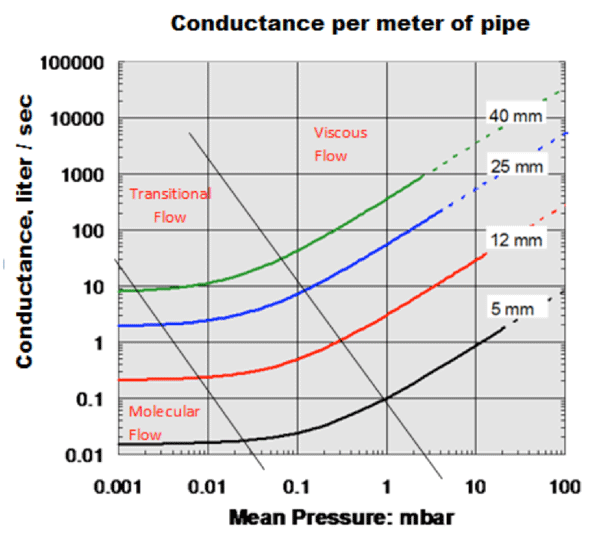
2. Conductance changes during the three modes of flow through the system (see fig 1). Three types of flow exist in vacuum systems: viscous or continuous flow, molecular flow and – at the transition between these two – Knudsen flow. The conductance in a given vacuum component is not a constant value but rather depends strongly on the nature of the flow. When calculating conductance, therefore, it is necessary to realize that only the conductance values applicable to a certain pressure range may be applied in that range.
The Three Modes of Flow
Viscous flow exists at higher pressures and is what we experience in non-vacuum systems. The pressure in this region is high enough that molecule-to-molecule collisions dominate the flow pattern. In the viscous flow region, the relationship between conductance and pressure is linear. When the pressure becomes lower, density drops. This decreased density increases the space between molecules, and the mean free path before molecule-to-molecule collisions occur is greater. For air at 20°C, the mean free path is approximately 66 nm at atmospheric pressure and increases as pressure falls. At 0.001 mbar it is approximately 6.6 cm. It is longer for lighter and hotter gases but pressure is the dominant quantity.

Molecular flow occurs as the pressure drops further, so the interaction between molecules no longer has an effect. Rather, molecule-wall collisions dominate.
Transitional flow takes place in-between viscous and molecular flow and is non-linear.
Conductance is greatest in the viscous flow region, the smallest in the molecular flow region, and in between for the transitional flow region. In other words, Cm < Ct < Cv. The pressure-geometry relationship defining the transition between viscous and molecular flow is not strictly demarcated but considered a general region between which the flow changes from the viscous region to the molecular region. For example, given a 5mm diameter pipe (Fig. 1), the flow is considered viscous above roughly 1.3 mbar, is considered molecular below approximately .027 mbar, and transitional in between.
Note the conductance is different for different diameters at the same pressure because conductance is dependent on both pressure and diameter. The same holds true for the regions considered viscous, molecular, and transitional. Also note that (a) in the molecular flow region, the graph is nearly flat and conductance is nearly independent of pressure (b) for viscous flow, conductance is a linear function of pressure and (c) in the transitional region the relationship between conductance is non-linear.
Calculating Conductance in Series and Parallel
It is the effective pumping speed (Equation 1) that shows that the smaller of S and C is the limit to pumping performance and merely increasing the pumping speed is not enough.
(1) 1/Seff = 1/S + 1/C or Seff = S*C/(S+C)
The total system conductance CT for components and pipes connected in series is calculated as follows, where the inverse of the system conductance is equal to the sum of the inverse of each the individual conductance values:
Therefore the system conductance can be expressed as:
For components and pipes in parallel, conductance is calculated as follows:
C = C1 + C2 + C3 …
Calculating Conductance in Orifices, Pipes, and Tubes
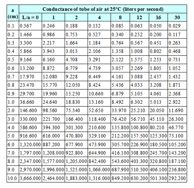
Data for calculating conductance in cylindrical pipes & tubes are readily available.2 It is important to note that the tabulated values may differ by as much as 12% from actual results for systems in free molecular flow.3 This is an acceptable error considering the other uncertainties in calculating pumping speeds relative to pressure for a given system.
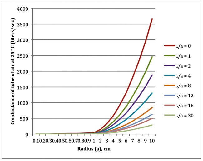
In looking at the tabular data in graphical form (Fig. 2), the molecular flow conductance (Equation 2) tells us that a = f (L/a) and so the effect of L/a is identical for all diameters. It should be stressed that these conductances are only for molecular flow (no such data exists in laminar flow) and that calculating by hand outside molecular flow is hard and prone to greater error.
(2) Ca • a
where Ca is the aperture conductance (dependent on area, gas RMM, and absolute temperature) and a is the transmission probability.
Even in the easiest cases in molecular flow, calculating conductance is far from simple and it is considerably harder at higher pressures in viscous flow. Unless one has a good understanding of the vacuum system and experience with similar systems it is advisable to consult a vacuum pump manufacturer who is able to use their experience in modeling systems. One such example is Edwards’ proprietary vacuum science modeling tools, PumpCalc® and TransCalc designed to verify calculations, identify best-fit pump solutions and optimize pump performance (e.g., pumpdown speed). These packages (not offered for sale) are used to support existing customers for modeling a wide range of vacuum system configurations, using more accurate and complex methods than those outlined here (Note: These products will be the subject of a separate article in this series).

Calculating Conductance
The conductance of an orifice is determined as follows:
- Measure the orifice’s radius in centimeters (“a” on the table).
- Find the table entry corresponding with the orifice diameter in the first data column (L/a = 0).
- For example, an orifice with a .8 cm radius has a conductance of 23.470 L/sec
The conductance of a straight cylindrical pipe or tube is calculated as follows:
- Measure the (overall) length (M) and radius (cm) of the pipe
- Divide the length by the radius, which provides the L/a ratio referenced in the table
- Find the table entry corresponding with the radius and the L/a ratio. If the exact match is not available, use the next larger “L/a” value or interpolate.
- Consider, for example, a 2-meter pipe with an ID of 1 cm. The radius “a” is equal to ½ the diameter or .5 cm. L/a is calculated as 2/0.5 = 4. From the table, the conductance is 13.160 L/sec

General Guidelines for Good Vacuum System Design
The following are simple rules of thumb when designing your system.
- Shorter length and larger diameter piping is best.
- Manifold and piping diameter should be the same as, or greater than, the inlet to the vacuum pump.
- The pumping system should be physically located as close as possible to the chamber.
- The number of bends, elbows, and turns should be kept to a minimum.
- Vacuum filter flow ratings should meet or exceed the CFM rating of the pumping system and must be kept clean.
- Find and use a previous reference project as a guide for the new one you are designing. This will allow you to empirically verify your design to the greatest extent possible, prior to investing in manpower and materials.
Final Thoughts
Conductance is seldom considered in designing and maintaining our pumping systems but is well worth the time to understand and the effects of which must be taken into consideration so as to create an optimum pumping system.
Also, see our blog on the Different Types of Vacuum Pumps Here
References
- Chew, Andrew “Conductance”, white paper, Edwards Vacuum, May 2015
- Dushman, Saul, Scientific Foundations of Vacuum Technique, 2nd Edition, (J. J. Laffery, Ed.), John Wiley & Sons, 1962, pg. 99.
- Lange, W. J., and J. H. Singleton, D. P. Eriksen, “Calculation of Low Pressure Penning Discharge Type Gauges, Vac. Sci. Tech., Vol. 4, No.3, pg. 338.
- Herring, Daniel H., Vacuum Heat Treatment, BNP Media Group, 2012.
- Herring, Daniel H., Vacuum Heat Treatment, Volume II, BNP Media Group, (in preparation).
- Wikipedia (www.wikipedia.org)
- “Pumping System Design”, American Vacuum Society Course


Comments
Be the first to comment...