
You have no items in your shopping cart
Proper Selection and Use of Vacuum Gauges
- Posted on
- Posted in Buyers Guides, Vacuum Pump
- 0
How to accurately measure (and control) the pressure at each stage of the process being performed.
Selecting the correct vacuum gauge or gauges is critical to the success of any process utilizing vacuum. It is important to know how they work and what options are available so that the correct choice can be made. There are several important considerations when using a vacuum gauge. They include the method of operation, the gas composition (inert or reactive, corrosive), the gas sensitivity (calibration factor), and the process being performed in your system.
Given the wide range of pressures required for many common vacuum processes, no one gauge is adequate over the entire range of possible vacuum levels. As with vacuum pumps, multiple gauges are necessary to properly cover the entire operating range with the needed precision and accuracy. Given that it is critical to monitor the vacuum pressure at various points in the process and perhaps multiple locations throughout the vacuum system, the correct selection of each gauge ensures that we achieve optimal results.
Other important considerations in gauge selection are performance and technical factors such as resolution, measurement range, accuracy (the range of systematic error), precision (the level of random error), lifespan and response time, as well as cost (as always).
Pressure Ranges
Different gauges are required for different operating ranges. The gauge selection depends on an understanding of the working principles of the gauge, the range of pressures it can measure, and its accuracy over the required range. These factors have been determined by experience and there is a vacuum gauge for every pressure range.
- For low (“rough”) vacuum ranges (higher pressures) between atmospheric and 10 Torr, Bourdon tubes, bellows, active strain gauges, and capacitance sensors are all suitable measurement devices.
- For mid-range vacuum requirements, those in the 10+1 Torr to 10-3 Torr range there are several choices including the capacitance manometer, for more accurate measurements, or the thermocouple or Pirani type gauges.
- For high vacuum, from 10-3 Torr to 10-6 Torr, either cold cathode or Bayard-Alpert hot cathode gauges are used. Both require frequent calibration.
- For ultra-high vacuum, below 10-6 Torr, cold cathode or Bayard-Alpert hot cathode gauges are also used.
Direct versus Indirect Acting Gauges
Gauges are divided into two categories, based on the way they measure pressure: those that directly measure pressure (the force exerted by impinging gas molecules) and those that indirectly measure pressure by measuring properties of gases that vary with pressure. Indirect gauges must be calibrated (i.e. have their readings adjusted) based on the actual gas present. Their readings are, therefore “gas type dependent”. Direct gauges are used in the low vacuum range and indirect gauges are used in the middle, high and ultra-high vacuum ranges.
Indirect gauges are further divided into the following groups:
- Those that measure molecular drag or viscosity (spinning rotor)
- Those that measure heat transfer through the gas (Pirani and thermocouple gauges)
- Those that measure number density by ionizing gas molecules, moving them to an electrical contact and measuring the resulting current such as cold-cathode gauges (i.e., Penning gauges) or hot-cathode ionization gauges).
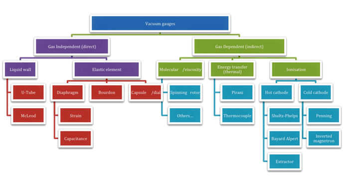
Figure 11 – The relationships and subcategories within the various vacuum gauge types
Before providing examples of the various types of direct and indirect-acting gauges, it is important to understand the basic principles of these gauges. We know that the vacuum level in a vessel is determined by the pressure differential between the evacuated volume and the surrounding atmosphere (Table 1). The two basic reference points in all these measurements are standard atmospheric pressure (760 Torr) and perfect vacuum (0 Torr) so calculations involving vacuum systems often require conversions to absolute pressure (psia) or negative pressure (psig).
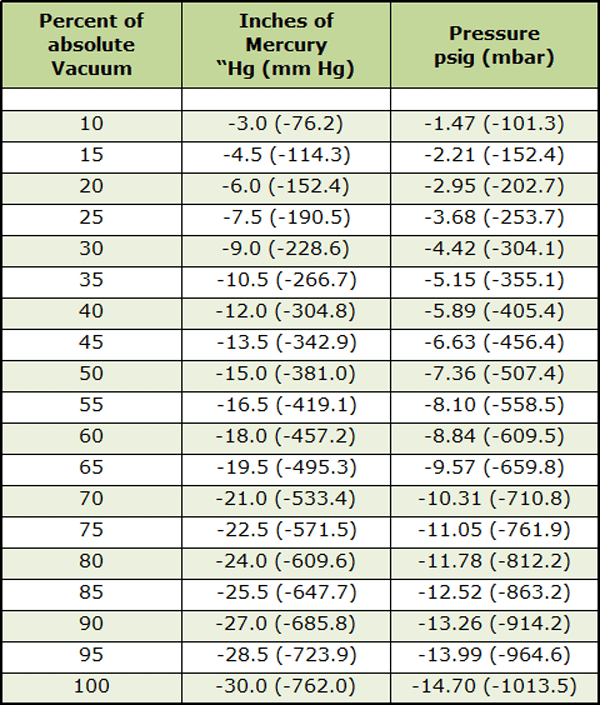
Table 12 – Comparison of vacuum and pressure levels
Using the Gas Sensitivity Factor with Indirect Acting Gauges
The calibration factor used to adjust the reading of indirect acting gauges is referred to as the gas sensitivity factor, which is provided by the gauge manufacturer and is dependent upon the gas type present. The sensitivity factor (usually in Torr-1) is only valid for the gas for which it is specified. The standard gas upon which the sensitivity factor is based is most often nitrogen. Thus the sensitivity factor is called the nominal relative sensitivity factor (Rg). Unless this factor is applied, all readings are considered to be “nitrogen-equivalent” pressures.
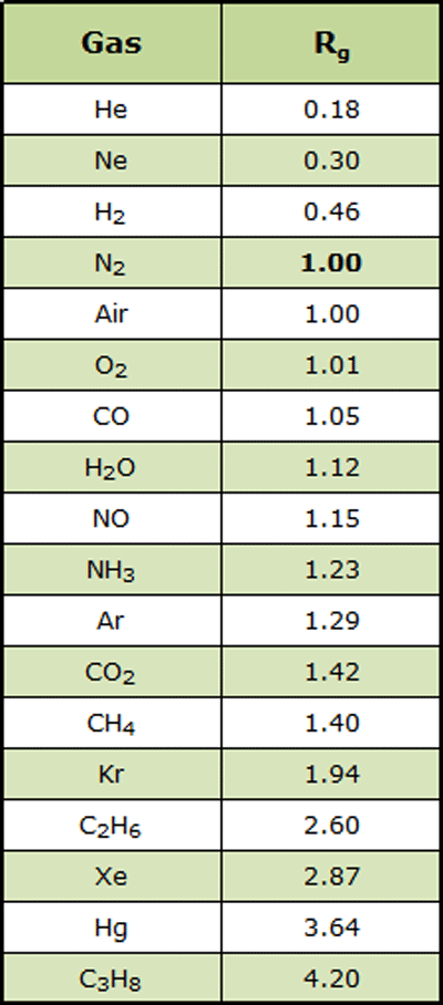
Table 23 – Nominal gas correction factors (N2 = 1.0)
Nominal relative sensitivity factors to convert nitrogen-equivalent readings into direct pressure readouts for gases other than nitrogen are available from most gauge manufacturers and other sources. Once the relative sensitivity factor is known, direct pressure readings are calculated.
For example, if the sensitivity for nitrogen is SN2 and the indicated (measured) pressure = PN2 then the sensitivity of the gas being measured (Sgas) is used to calculate the true gas pressure (= Pgas) for any gauge (Equation 1).
SN2
(1) P True (gas) = ——— PN2
Sgas
In the case where SN2 = 1 then simply: PTrue (gas) = Pindicated(N2)/Sgas
For calibration of ionization gauges where the collector and emitter current are known, the following equation applies:
(2) P = [ Ic / (Sg · Ie)]
Where:
Sg is the sensitivity factor for gas ‘g’ [Torr-1]. Here Sg = SN2 · Rg
SN2 is the sensitivity factor for nitrogen [Torr-1] Rg is the gas correction or relative sensitivity factor (Table 2)
Ic is the ion collector current [amps] Ie is the electron emission current [amps]
In the following section, we focus on the types of gauges in use throughout the heat treatment industry including their function and application.
Types of Gauges
There are three common types of gauges used in heat treatment, namely mechanical, thermal conductivity, and ionization gauges. Each is unique and well suited for its intended purpose.
Mechanical gauges. The use of mechanical displacement to indicate pressure is considered a type of “direct acting” gauge. Examples are Bourdon gauges, U-tube and capacitance diaphragm manometers. They measure the force per unit area utilizing Dalton’s law: “Total pressure of a mixture of gases equals the sum of the partial pressures of each gas”. Direct acting gauges are not subject to the issue of gas sensitivity and do not need to be calibrated for the gas being measured. Their sensitivity is such that they are not used in the high vacuum range (below ~10-4 mbar).
Active Inverted Magnetron Gauge (AIM)
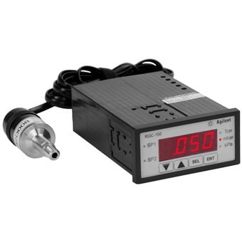
Thermal Conductivity gauges. These gauges represent a class of “indirect acting” gauges. They use the property of thermal conductivity of gases to measure the pressure. One example is the Pirani gauge, in which a platinum filament is heated, and its heat loss to the vacuum environment is measured. The rate at which heat is conducted away from the wire is directly related to the pressure being measured. At lower pressure and reduced density, the gas in the vacuum chamber conducts the heat away more slowly. At higher pressures the wire will lose its heat more quickly. A second platinum filament, contained in a vacuum tube, is used as a reference. The two filaments are wired in a Wheatstone bridge. When gas molecules in the vacuum system collide with the exposed filament, thermal energy is conducted away, and this loss in thermal energy is detected and replaced by the feedback circuit to the power supply. The amount of electrical current needed to maintain the filament temperature is then converted to a pressure readout. Pirani gauges must be calibrated for the gas being used because the thermal conductivity since each gas is different. This “gas sensitivity” must always be considered when selecting and using indirect acting gauges. This type of gauge is used for pressures between (approximately) 100 Torr and 10−4 Torr. Pirani gauges (Fig. 2) relate the heat lost by the platinum filament to the pressure (Equation 1)7.
(1)
.gif)
Where
Cfil is the heating capacity of the filament,
Mfil is the mass of the filament
C1 and C2 are constants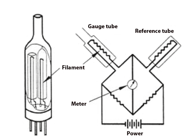
Figure 28 – Pirani Gauge
Another type of thermal conductivity gauge is the thermocouple gauge (Fig. 3), which is considered a two-wire gauge. It uses the same principle as the Pirani gauge (a one-wire gauge), except that one wire coil is used as a heater, and the other is used to measure temperature due to convection. Thermocouple gauges and thermistor gauges use a thermocouple or thermistor, respectively, to measure the temperature of the heated wire. Once again, the rate of heat lost by the wire is converted into a pressure and is therefore dependent on the gas constituents of the vacuum range being measured and must be calibrated accordingly.
The convection gauge is also similar to the Pirani gauge, and uses a temperature-compensated, gold-plated tungsten wire to detect the cooling effects of both conduction and convection. At higher vacuum, the response depends on the thermal conductivity of the gas, while at lower vacuum it depends on convective cooling by the gas molecules. Measurement range is from 10-3 to 1,000 Torr. With the exception of its wider sensing range, features and limitations of this sensor are the same as those of Pirani and most thermocouple gauges. This sensor must be mounted vertically.
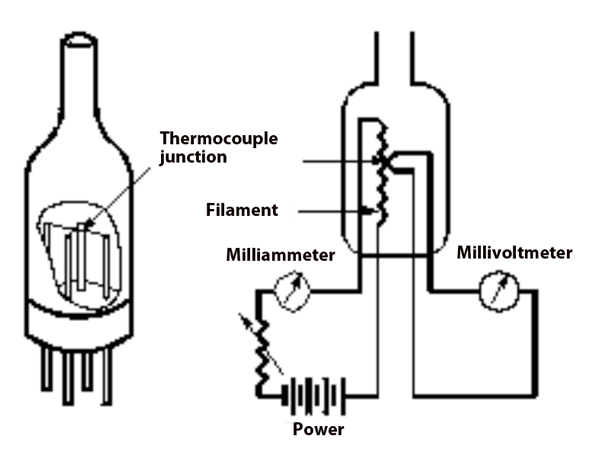
Figure 39 – Thermocouple Gauge
Pirani, thermocouple and convection gauges are very commonly used in a rough and medium vacuum because they are inexpensive and relatively robust. However, the user must remember to apply the gas sensitivity factor, otherwise, there can be large errors at the high and low extremes of their measurement range.
These are non-linear gauges and as such the Sgas used has to allow for this (Fig. 4) .
The gas sensitivity of a convection gauge also varies depending on the gas in use (Fig. 5). Here the Y- axis of the graph is actual pressure (measured by a capacitance manometer). The X-axis is the pressure reading indicated by a particular convection gauge. Note this data does not necessarily apply to other convection gauges.
- If the gas is nitrogen (N2), when the true total pressure is 500 Torr, the gauge will read 500 Torr.
- If the gas is argon (Ar), when the true pressure is 100 Torr, the gauge will read approximately 9 Torr.
- If the gas is helium (He), when the true pressure is 10 Torr, the gauge will read approximately 800 Torr.
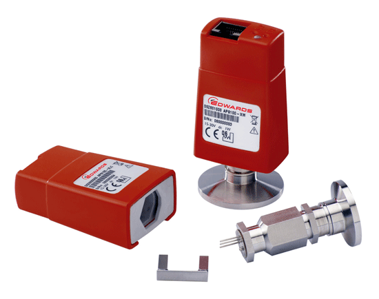
Ionization Gauges. There are two types of cold-cathode ionization gauges: the Penning gauge and the inverted magnetron. The Penning gauge is the style most often used in vacuum furnaces. Hot cathode ionization gauges can also be used and will be the subject of a future discussion.
Ionization gauges are relatively accurate at high vacuum and are an indirect-acting type of gauge. They sense pressure indirectly by measuring the electrical ions produced when the gas is bombarded with electrons. Fewer ions will be produced by lower density gases. In an ionization gauge, thermionic emission generates electrons, which collide with gas atoms and generate positive ions. The ions are attracted to a suitably biased electrode known as the collector. The current in the collector is proportional to the rate of ionization, which is a directly related to the pressure in the system. By measuring the collector current, the gas pressure is determined. The calibration of an ion gauge is dependent on the properties and proportion of the different gases in the vacuum being measured. Penning gauge calibration is also sensitive to physical geometry, corrosion and surface deposits. Further their calibration can be invalidated by activation at atmospheric pressure or low vacuum.
Cold-cathode gauges such as Penning gauges may not start at very low pressures due to the fact that the near-absence of a gas makes it difficult to establish an electrode current. Penning gauges use an axially symmetric magnetic field to create path lengths for electrons that are of the order of meters. In ambient air, suitable ion pairs are formed by cosmic radiation. In a Penning gauge, design features are used to ease the set-up of a discharge path. For example, the electrode of a Penning gauge is usually finely tapered to facilitate the field emission of electrons.
Maintenance cycles of Penning gauges are, in general, measured in years, depending on the gas type and pressure that they are operated in. Using a cold cathode gauge in gases with substantial organic components, such as pump oil fractions, can result in the growth of delicate carbon films and shards within the gauge that eventually either short circuit the electrodes of the gauge or impede the generation of a discharge path. To help resist against failure due to buildup or debris, these gauges are typically mounted in the vertical down orientation. Penning gauges are accurate in the range of 10-3 to 10-10 Torr.
Where are Vacuum Gauges in a Furnace System and Why?
We now look at the purpose of each specific gauge in a typical vacuum system.
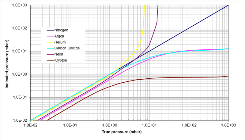
Figure 45 – Relationship of various gases in a Pirani gauge to the true vacuum pressure
Foreline Gauge
The first step of a vacuum furnace pumping cycle is generally to evacuate the oil diffusion pump to a low enough pressure that the heaters can be switched on. To monitor that pressure, a Pirani, thermocouple or convection gauge is located in the vacuum piping near the exhaust connection of the diffusion pump. This pipeline is called the foreline (of the mechanical pump) or the discharge line (of the diffusion pump). Later in the furnace process cycle, when the diffusion pump is up to operating temperature, the vacuum furnace exits the low vacuum phase and enters high vacuum.
As the crossover is made from roughing to high vacuum pumping, the foreline gauge is used to monitor the diffusion pump discharge pressure. Oil diffusion pumps work with hot oil vapor jets and the discharge pressure must be kept below the critical discharge pressure of the pump and fluid used for the vapor jets to work correctly. The foreline gauge is used to close the high vacuum valve if the discharge line pressure approaches the critical discharge pressure.
Chamber Roughing/Crossover Gauge
The chamber roughing (i.e., crossover) gauge type can be a thermocouple, Pirani or convection style. It is mounted on the vacuum chamber to measure the pressure attained during the low vacuum phase of the process. This is the second step of the evacuation, when the mechanical pumps are directly connected to the chamber through the roughing line.
Once the diffusion pump has heated up and is pumping against the closed vacuum chamber, the foreline valve is closed and the roughing valve opened to allow the mechanical vacuum pump to bring the furnace down to the crossover pressure. In small systems, this may take only a few minutes and with clean oil and minimal outgassing, the pressure in the discharge line will stay below the critical discharge pressure. For higher volume furnaces, the roughing cycle will take longer. To ensure that the critical discharge pressure is not exceeded while the main mechanical pump is on the roughing cycle, a small 0.14-0.28 m3/min (5 to 10 cfm) mechanical holding pump is included at the discharge side of the diffusion pump to keep the discharge pressure at a safe level.
High Vacuum Gauge
The third gauge is commonly known as an ionization gauge or capacitance manometer and is used to measure high vacuum. The best location of the vacuum gauge is partly dependent on what is mounted inside the chamber. It would be ideal to know the pressure near the load in the center of the chamber. The gauge head, however, must be mounted on the outside of the chamber and can only measure the vacuum in its own envelope. As a result, it is understood there is a difference between the desired process vacuum and the gauge reading. Therefore the gauge reading determining when vacuum is reached must be determined empirically and is based on experience once this variance is understood.
To minimize this variance, the gauge head should be located as close to where the measurement is needed as possible, which can be a challenge in processes such as vacuum deposition where the gauge interior could be contaminated by the material being evaporated or sputtered. A solution to this is to mount a small line-of-sight shield inside the chamber near the gauge head. Another challenge with Penning gauges is in that they must not be turned on until the pressure is at approximately 10-2 Torr or below. They will be damaged at pressures above 10-2 Torr due to the fact that there is sufficient oxygen present in the chamber to oxidize the gauge head and short it out.
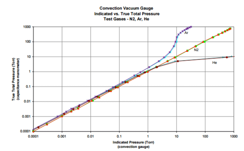
Figure 510 – Difference between measured pressure and actual (true) pressure with different gases, due to gas sensitivity
Mechanical Vacuum Pump Gauge
A fourth vacuum gauge is mounted near the mechanical vacuum pump inlet on the pump side of an isolation valve. If the vacuum system doesn’t pump down to the expected pressure or in the expected time, the mechanical pump operation must be checked, and this gauge is used for this purpose. This also should be done for the mechanical booster pump if one is mounted above the mechanical pump. It is always helpful to locate a gauge near the pump inlet to allow problem diagnosis and check the pump for proper operation. Over time, the gauge can be contaminated by oil vapor from the mechanical pump. To prevent this, a temporary gauge is installed and removed after use. The system piping is designed with a temporary connection point for the gauge and an isolation valve to shut off the tee when not in use. Portable battery operated gauges are available for this purpose.
Summary
The subject of vacuum gauges is a broad one, and while we have only covered the basics, the implication is clear – to make the most effective use of your pumping systems, you must accurately measure (and control) the pressure at each stage of the process being performed.
Also, see our blog on the Different Types of Vacuum Pumps Here
References
- Chew, Andrew, “Calibration Factors for Vacuum Pressure Gauges, Edwards Vacuum LLC, September 2015.
- Herring, Daniel H., Vacuum Heat Treatment, BNP Media Group, 2012.
- “Gas Correction Factors for Bayard-Alpert Ionization Gauges”, Stanford Research Systems (www.thinksrs.com)
- Brunner Jr., William F. and Batzer, Thomas H., Practical Vacuum Techniques, Robert E. Krieger Publishing Company, 1974.
- Chew, Andrew, “Calibration Factors for Vacuum Pressure Gauges, Edwards Vacuum LLC, September 2015.
- Herring, Daniel H., Vacuum Heat Treatment, BNP Media Group, 2012.
- Patent DE 10115715, Plöchinger, Heinz, “Sensor and Method for Detecting Measurement Variables and Physical Parameters”, 2001 – 2002.
- University of Alabama (http://bama.ua.edu/~surfspec/vacbasics.htm)
- National Instruments (www.ni.com)
- InstruTech, Inc., The Super Bee™ operating manual (www.instrutechinc.com)
- Brunner Jr., William F. and Batzer, Thomas H., Practical Vacuum Techniques, Robert E. Krieger Publishing Company, 1974.
Comments
Be the first to comment...